TECHNICAL GUIDES (v1.4)
- INTRODUCTION AND OVERVIEW
- MODEL DEVELOPMENT
- SUBMISSION SELF-ASSESSMENT
- FORMAL SUBMISSION
- SOFTWARE-SPECIFIC TECHNICAL GUIDELINES
INTRODUCTION AND OVERVIEW
INTRODUCTION
PURPOSE OF THE GUIDES
These Technical Guides support the implementation of the Dubai BIM Standard by providing practical instructions for model development, IFC preparation, pre-submission validation, and submission.
While the Dubai BIM Standard defines regulatory requirements, information purposes, and compliance criteria, these Technical Guides explain how permit applicants can achieve compliance using BIM authoring tools and openBIM workflows.
The Technical Guides do not replace the Dubai BIM Standard. In case of conflict, the Dubai BIM Standard shall take precedence. Users of these Technical Guides should use this document in conjunction with the relevant Dubai BIM Standard appendices, templates, and submission checklists to ensure full compliance.
The Technical Guides may be updated periodically. Users shall ensure they are using the latest version for all new projects.
HOW TO USE THIS DOCUMENT
The Technical Guides are organised into separate parts and sections covering different aspects of BIM model development and submission requirements.
This document is structured as a reference guide and is not intended to be read sequentially. Users should refer directly to the sections relevant to their role, task, or stage of submission.
DOCUMENT STRUCTURE OVERVIEW
This document is divided into four parts:
INTRODUCTION
This part provides overall context and preparation guidance, including:
Purpose and scope of the Technical Guides
Relationship between the Dubai BIM Standard and these guides
Key preparation steps prior to model development and submission
MODEL DEVELOPMENT
This part defines the technical requirements for BIM model creation, including:
General requirements
Geometrical information requirements
Alphanumerical information requirements
Classification requirements
Model segregation and georeferencing principles
SUBMISSION SELF-ASSESSMENT
This part defines the requirements for model self-assessment and validation prior to formal submission.
Users should perform offline self-assessment and QA/QC checks before proceeding with any online validation and submission process
SUBMISSION
This part defines the procedure for preparing BIM submissions and uploading them to the platform for formal review.
SOFTWARE-SPECIFIC TECHNICAL GUIDELINES
This part provides technical guidance for the preparation of BIM models using common BIM authoring software. The guidance provided is not exhaustive, and users are expected to have sufficient knowledge and experience in the use of their selected BIM tools to ensure compliance with the requirements.
TECHNICAL SUPPORT
Where the guidance provided in this document does not adequately address specific project requirements or user needs, additional technical support may be sought from Dubai Municipality.
Where necessary, users may also request an online meeting to discuss complex or project-specific issues by submitting a ticket on GeoDubai Service using BIM technical support services. Alternatively, support requests can be sent to geodubai@dm.gov.ae.
This support mechanism ensures that users can obtain timely assistance while maintaining compliance with the Dubai BIM standard.
FEEDBACK
The Technical Guides aim to comprehensively cover all requirements necessary for preparing BIM submissions in accordance with the Dubai BIM Standard.
If users identify any gaps, unclear guidance, or missing topics within this document, they are encouraged to provide feedback. All feedback will be reviewed and considered for future updates to ensure the continuous improvement and relevance of the Technical Guides.
SUBMISSION WORKFLOW OVERVIEW
This section provides an overview of the workflow for developing BIM models for submission to the Dubai BIM E-Submission Platform.
The workflow is software-independent and applies to all BIM authoring tools. It defines the key steps required to ensure that BIM models comply with the applicable standards and submission requirements.
Detailed technical guidance for each step is provided in the subsequent sections of this document.
PREPARATION
Before starting a new submission, users shall review the Dubai BIM Standard documents to understand the applicable requirements and compliance criteria.
Users should also review available online BIM submission workshops and guidance materials, which are available on Build in Dubai Platform, as these provide practical demonstrations of the submission process and requirements.
For first-time submitters, reviewing the provided sample models is strongly recommended to understand the required Level of Information Need and modelling practices.
Failure to review these materials may result in non-compliant submissions and validation errors.
DOWNLOAD BIM E-SUBMISSION TEMPLATE
Before starting model development, users should download and use the latest BIM E-Submission templates where available.
Templates are currently provided for the following BIM authoring tools: Revit, Archicad, and Bentley OpenBuildings Designer.
Each template includes predefined properties, settings, views, and object configurations to support consistent and efficient model creation.
The use of these templates is not mandatory. However, their use is recommended, as they improve model consistency, data completeness, and the likelihood of successful submission and approval.
MODEL DEVELOPMENT
Once the required preparation steps have been completed, BIM model development can begin in accordance with the requirements defined in PART 2 of this document.
Key activities include:
Geo referencing: Users should establish project georeferencing at the start of the modelling process to avoid major adjustments at later stages.
Model Creation: The BIM model shall be developed in accordance with the required Level of Information Need (LOIN) defined in the Dubai BIM Standard. Sample models may be used as reference, particularly for first-time users.
Model Segregation: The model shall be structured in accordance with the model segregation requirements defined in Section 2.5.
MODEL IFC EXPORT
The export of the BIM model to IFC format is a critical step prior to submission.
Users shall ensure that the IFC export is performed using the correct export settings and configurations to preserve geometry, classification, and alphanumerical information.
Incorrect export settings may result in visualization issues, data loss, or validation errors during submission.
SUBMISSION SELF-ASSESSMENT
Before formal submission, users shall perform a self-assessment of the IFC models to verify model quality and compliance with the applicable requirements.
Users shall carry out offline QA/QC checks prior to uploading the model to the platform. This allows identification and correction of issues without initiating the online validation process.
Detailed requirements for self-assessment and QA/QC checks are provided in PART 3.
Models with unresolved critical issues should not be submitted to the BIM E-Submission Platform.
FORMAL SUBMISSION
This stage involves the formal submission of BIM models to the BIM E-Submission Platform for review.
Users shall ensure that all submission files are prepared, packaged, and named in accordance with the specified submission requirements prior to upload.
Detailed submission procedures and requirements are provided in Part 4 of this document.
MODEL DEVELOPMENT
INTRODUCTION
Part 2 defines the technical requirements for developing BIM Information Models intended for submission to the Building Permit Authorities, in accordance with the Dubai BIM Standard (Part 2 – Exchange Information Requirements). Compliance with this part is mandatory for all BIM submissions.
This part translates the requirements of the BIM Standard into practical modelling rules to support the preparation of compliant IFC models suitable for regulatory review, automated validation, and digital workflows.
All model development activities shall ensure that the BIM Information Model:
Is prepared in accordance with the Level of Information Need (LOIN) defined in the BIM Standard
Contains sufficient geometrical and alphanumerical information to support its intended use
Is structured, classified, and organised to enable interoperability and automated processing
The modelling requirements set out in this part shall be applied in conjunction with the following appendices:
Appendix A – Model Element Matrix
Appendix B – Model Attribute Matrix
Appendix C – Usage Codes
These supporting documents define the detailed requirements that govern model content, structure, and information completeness. This part is primarily intended for:
BIM authors
BIM coordinators
Discipline leads responsible for BIM Information Model development
LEVEL OF INFORMATION NEED (LOIN)
The Level of Information Need (LOIN) defines the minimum required information within BIM Information Models submitted for building permit assessment. The detailed requirements are defined in the Dubai BIM Standard.
LOIN shall be implemented at the model element level. Each element within the model shall independently satisfy the required geometrical and alphanumerical information defined in:
Appendix A – Model Element Matrix
Appendix B – Model Attribute Matrix
Model authors shall ensure that:
All elements required for the permit submission are modelled
Each element contains only the information necessary for its intended regulatory use
The information required for validation is not missing, incorrect, or incomplete
No unnecessary or excessive information that is not required for regulatory assessment is modelled, as this may negatively impact model performance and processing efficiency
ALPHANUMERICAL INFORMATION
Alphanumerical information shall be assigned to all model elements in accordance with Appendix B – Model Attribute Matrix and shall be correctly exported to IFC property sets.
Each model element shall:
include all required attributes
be mapped to correct IFC class and type
PROJECT INFORMATION
Project-level attributes are mandatory and are used for BIM E-Submission processing, validation and Building Card generation. Missing or incorrectly populated information may result in critical validation errors during model review. Project information shall be exported as IfcProject.
The following key attributes must be populated (for the full list, refer to Appendix B):
ParcelId: This attribute represents the official land parcel identification number issued by the Authority. The value shall match the ParcelId used in the IFC file name, with no discrepancies.
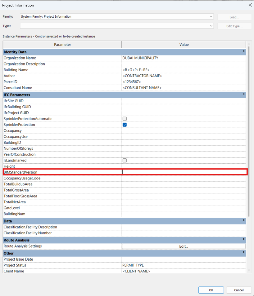
BIMStandardVersion: This attribute identifies the version of the Dubai BIM Standards used during model preparation. The latest published version (e.g. 1.4) shall be used for all new BIM submissions.
SITE INFORMATION
Site information defines the geographical context of the project and is required for georeferencing and validation within the BIM E-Submission. Site information shall be exported as IfcSite.
The following attribute must be populated:
- GateLevel: This parameter represents the approved Gate Level elevation for the project and shall be entered in meter. The value shall match the elevation assigned to the GA_GATE LEVEL within the BIM model to ensure consistency.
BUILDING INFORMATION
Building-level attributes are required for classification, validation, and Building Card generation within the BIM E-Submission.
Building information shall be exported as IfcBuilding.
In cases where multiple towers share a common podium or basement, and each part is exported to a separate IFC file, all IfcBuilding entities associated with the same submission shall contain consistent Building Information.
The following key attributes must be populated (for the full list, refer to Appendix B):
SprinklerProtection: A Boolean attribute indicating whether the building is protected by a sprinkler system. The value shall be set to YES where sprinkler protection is provided, and NO where it is not. For most building types, this parameter is typically expected to be YES.
YearOfConstruction: This attribute represents the year in which construction of the building is intended to commence.
IsLandmarked: A Boolean attribute indicating whether the building is classified as a landmarked or historically protected structure. The value shall be set to YES for landmarked buildings and NO for standard development projects.
Height: This attribute represents the building height measured from the approved road edge level at the main plot access to the highest roof surface or element. The value shall be entered in meters.
BuildingNum: This attribute is used to identify and group buildings belonging to the same project development. For projects containing multiple buildings, values shall be assigned incrementally, starting from 1. Where a single building is exported into multiple IFC files, all corresponding IFC files shall contain the same BuildingNum value. Refer to the Model Segregation outlined in Section 2.5 for details.
Occupancy: This attribute represents the Master Usage classification of the building. Values shall be obtained from the “Building” sheet within Appendix C – Usage Codes and shall be copied exactly without modification. For mixed-use developments, multiple values shall be entered as comma-separated entries. For example, in a mixed-use residential project comprising apartments, shops, and offices, the Occupancy value shall be entered as “Residential, Commercial”.
OccupancyUse: This attribute represents the Main Usage classification corresponding to the selected Master Usage categories. Values shall be obtained from Appendix C – Usage Codes and entered exactly as defined. For mixed-use developments, multiple values shall be entered as comma-separated entries. For example, in a mixed-use residential project comprising apartments, shops, and offices, the OccupancyUse value shall be entered as “Residential Apartments,Shops,Offices”.
OccupancyUsageCode: This attribute represents the code associated with the selected Main Usage classification. Values shall be obtained from Appendix C – Usage Codes and entered exactly without modification. Where multiple Main Usage categories exist, all corresponding codes shall be entered as comma-separated values. For example, in a mixed-use residential project comprising apartments, shops, and offices, the OccupancyUsageCode value shall be entered as “MS_01_01, MS_03_02, MS_03_04”.
Area Attributes:
The attributes TotalBuiltUpArea, TotalGrossArea, TotalFloorGrossArea, and TotalNetArea shall represent manually calculated building total area values in accordance with the Dubai Building Code.
All values shall be entered in square meters (sqm).
These values will be compared against automated calculations generated by the BIM E-Submission Platform during validation.
In cases where multiple towers share a common podium or basement, the area parameters shall represent the total values for the entire building and shall not be assigned per individual part..
LEVEL INFORMATION
Levels (also referred to in this document as storeys) are fundamental elements within BIM models, as they provide the primary reference for element hosting and spatial organisation.
Each physical floor or storey within the building shall be represented in the IFC model as a corresponding IfcBuildingStorey entity and assigned a unique level name.
Dummy or reference levels may be created within the native BIM model to support modelling workflows. However, such levels shall not be exported to IFC.
It shall be ensured that all model elements are correctly hosted to their corresponding levels throughout the modelling process. Incorrect level hosting may result in inaccurate automated calculations, IFC hierarchy issues, and validation failures during BIM E-Submission.
The following key attributes must be populated (for the full list, refer to Appendix B):
Area Attributes:
The parameters TotalBuiltUpArea, TotalGrossArea, TotalFloorGrossArea, and TotalNetArea shall represent manually calculated area values for the corresponding Building Storey in accordance with the Dubai Building Code.
All values shall be entered in square meters (sqm).
BuildingPartNum:
This is a conditional attribute used to identify Building Storeys belonging to different building parts.
It must be applied where multiple building parts exist (e.g. podium and towers or interconnected structures).
Where multiple building parts share common levels and each building part exported as a separate IFC model, different BuildingPartNum values shall be assigned appropriately to the corresponding Building Storeys before exporting to IFC.
The parameter value shall be assigned incrementally. Refer to the Model Segregation outlined in Section 2.5 for details.
LEVEL NAMING
Each building level shall be clearly named to identify the corresponding floor or storey within the project. All BIM submissions shall comply with the level naming convention defined within the Dubai BIM Standard and shall remain consistent across all submitted BIM models.
Level names shall consist of two mandatory fields: Level Abbreviation and Level Identification, separated by an underscore (_). For example: F1_FLOOR1.
The Level Abbreviation field shall identify the level designation and shall use upper-case characters only.
The Level Identification field shall describe the corresponding level based on the abbreviation used. The wording may be defined by the user in accordance with their internal project standards, provided that it is clear, unambiguous, and consistently applied across the project.
Figure below shows an illustration of correct level naming.
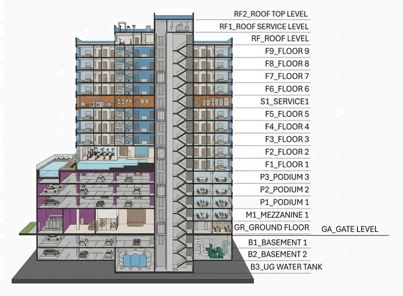
Figure 1. Illustration of correct level naming
SPACE/ROOM INFORMATION
Space/Room information is a critical component of the BIM E-Submission process. It is used by the platform for the automated generation of the Building Card, spatial validation, and area calculations.
All Space/Room parameters must be populated in accordance with Appendix B – Model Attribute Matrix and Appendix C – Usages Codes.
Usage values provided within Appendix C – Usages Codes shall be used exactly as defined without modification to ensure consistency across all BIM submissions and to enable proper automated compliance checking. Where an appropriate Space/Room usage cannot be identified, the Model Author shall coordinate with the Authority prior to submission for the values to use.
SPACE/ROOM NAME
Each Space/Room element shall be assigned a clearly defined and meaningful name that accurately reflects its intended function. Although the Dubai BIM Standard does not mandate a fixed space naming convention, the naming shall be:
Clear and easily understandable
Aligned with the design intent
Consistent throughout the project
Aligned, where applicable, with the corresponding SpaceUsageDescription defined in Appendix C.
SPACE MAPPING
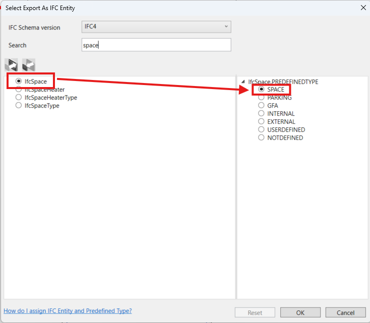
Space/Room elements shall be exported to IFC as “[IfcSpace”]{.underline}, with the PredefinedType set to “[SPACE]{.underline}”.
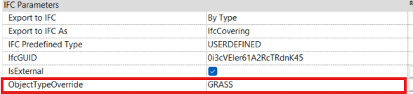
All spaces shall be correctly mapped to the appropriate IFC classification and exported using IFC4 Schema. This includes defining the appropriate PredefinedType where it exists within the IFC schema. Where a standard PredefinedType does not exist, or where further specification is required, the ObjectTypeOverride attribute shall be used to provide additional classification details.
Refer to Appendix B to see the list of ObjectTypeOverride available for Spaces.
SPACE [BUILDING OCCUPANCY ATTRIBUTES]
Space-level occupancy attributes shall be consistent with the building-level Occupancy, OccupancyUse, and OccupancyUsageCode attributes. Any inconsistency between building and space occupancy attributes may result in validation errors and incorrect Building Card generation
Each Space/Room shall be assigned only the occupancy values applicable to its specific function.
The following key attributes must be populated (for the full list, refer to Appendix B):
BuildingOccupancyUsageCode: This value shall be obtained from the “Building” sheet in Appendix C – Usage Codes and must be included in the building-level OccupancyUsageCode.
BuildingOccupancyUsageDescription: This attribute must be populated using the description corresponding to the selected BuildingOccupancyUsageCode, as defined in Appendix C.
For spaces serving multiple occupancies, values shall be entered as comma-separated entries.
Table 1. Sample of BuildingOccupancyUsagecode
| Example | BuildingOccupancyUsagecode | BuildingOccupancyUsageDescription |
|---|---|---|
| A Space/Room within a building with Master Usage as Residential Apartment | MS_01_01 | Residential Apartments |
| A Space/Room serves multiple occupancies within a building with Master Usage as Residential, Commercial | MS_01_01,MS_03_02 | Residential Apartments,Shops |
SPACE [USAGE ATTRIBUTES]
All spaces shall be assigned a valid Space Usage classification from Appendix C.
The following key attributes must be populated (for the full list, refer to Appendix B):
SpaceUsageCode: Values shall be obtained from the “Space” sheet in Appendix C – Usage Codes.
SpaceUsageDescription: This attribute shall contain the description corresponding to the selected SpaceUsageCode, as defined in Appendix C.
A few samples are listed below:
Table 2. Sample of SpaceUsageCode
| Zone Category | SpaceUsageDescription | SpaceUsageCode |
|---|---|---|
| Amenities | Hypermarket | SC_10_10_10 |
| Circulation Areas | Entrance | SC_15_10_15 |
| Hygiene Areas | Toilet | SC_20_10_50 |
| Living Space | Living Room | SC_25_15_10 |
| Other Areas | Parking | SC_30_10_15 |
| Retailing Area | Shop | SC_35_10_10 |
| Technical Services | Water Meter | SC_40_20_15 |
| Vertical Penetrations | Elevator (Lift opening) | SC_45_10_25 |
SPACE [ZONE ATTRIBUTES]
Zone information should be populated after the appropriate Space Usage Code has been identified.
Each Space Usage category corresponds to a predefined Zone Category listed in Appendix C. Once the Zone Category is identified, the corresponding Zone information shall be referenced from the “Zone” sheet within Appendix C.
The following parameters are associated with Zone Information:
ZoneName: Value shall be selected from Appendix.
ZoneObjectType: Value shall be selected from Appendix C.
Table 3. Applicable Zone Categories
| Zone Category | ZoneName | ZoneObjectType |
|---|---|---|
| Amenities | SC_10 | Amenity |
| Circulation Areas | SC_15 | CirculationArea |
| Hygiene Areas | SC_20 | HygieneArea |
| Living Space | SC_25 | LivingSpace |
| Other Areas | SC_30 | OtherArea |
| Retailing Area | SC_35 | RetailingArea |
| Technical Services | SC_40 | TechnicalService |
| Vertical Penetrations | SC_45 | VerticalPenetration |
| Workspace | SC_50 | Workspace |
SPACE [UNIT ATTRIBUTES]
Unit Information must be populated for all Spaces/Rooms that belong to an individual unit, amenity, or common functional facility within the project.
Unit Information enables the BIM E-Submission Platform to group and validate spaces associated with the same operational or occupancy unit.
A unit represents a group of spaces associated with a single functional entity, for example:
For residential developments, each apartment shall be treated as an individual unit, and all Spaces/Rooms belonging to the apartment shall contain identical Unit Information values.
Common amenities and recreational facilities such as swimming pools, gyms, children’s play areas, theatres, and similar shared facilities shall also be treated as separate units.
For office developments, each office tenancy or office area shall be considered a single functional unit. Shared facilities such as common toilets, cafeterias, prayer rooms, and similar common-use spaces shall also be assigned Unit Information where applicable.
For educational buildings, classrooms, teachers’ rooms, activity areas, play areas, laboratories, and similar functional spaces shall be treated as units.
All Spaces/Rooms within the same unit shall have identical Unit Information values. Unit information is not required for spaces classified under TechnicalService, common CirculationArea, and VerticalPenetration.
The following key attributes must be populated (for the full list, refer to Appendix B):
UnitNo: Identifies the unit number. Not required for spaces that do not belong to a unit.
UnitUsageCode: Value shall be obtained from the “Unit” sheet in Appendix C.
UnitUsageDescription: Corresponding unit usage description from Appendix C. When a value is not available for UnitUsageCode (e.g. RE_90), the unit usage description (“Others”) can be replaced with a custom description.
UnitExtraInfo: Additional information must be populated as per Appendix C templates. Where no value is required, the field shall remain empty. Where a predefined template format is provided, the values shall be updated according to the project design.
When [IsAreaLessThan150:Y/N],[Persons:?] template apply, UnitExtraInfo attribute should be provided using the template. E.g. [IsAreaLessThan150:Y],[Persons:2]
When [Persons:?],[Showers:?],[WCs:?],[Sinks:?] template apply, UnitExtraInfo attribute should be provided using the template. E.g. [Persons:3],[Showers:2],[WCs:1],[Sinks:3]
All Unit Information values (except UnitNo) shall be obtained from Appendix C – Usage Codes. UnitNo shall be assigned based on project design intent. For residential apartments, the apartment number may be used directly. For amenities and common facilities, sequential numbering may be applied considering the facility type and hosted level.
Unit information shall be selected based on the approved Master Usage of the project. For example, where the project Master Usage is Residential, only the Unit information corresponding to Residential within the Appendix C “Unit” sheet shall be used.
SPACE [OTHER ATTRIBUTES]
Several attributes associated with Space/Room information are defined as Boolean data types. In some BIM authoring tools, Boolean parameters may appear undefined or unassigned when no value has been explicitly set. All Boolean parameters shall be explicitly assigned a value. Where a Boolean parameter is not applicable, it shall be set to NO unless specified otherwise.
Failure to define Boolean values may result in missing attributes in the IFC export and validation errors.
The following Boolean attributes must be populated where applicable:
PubliclyAccessible: Identifies whether the Space/Room is accessible to general occupants or the public.\ Example: Amenities within residential developments are generally accessible for all occupants, while apartment units, technical rooms, and MEP service areas are typically limited access spaces.
IsExternal: Identifies whether the Space/Room is located outside the enclosed building envelope
HandicapAccessible: Identifies whether the Space/Room is accessible for People of Determination in accordance with accessibility requirements.
FireExit: Identifies whether the Space/Room forms part of the fire escape or emergency egress route, including fire stairs, fire lift lobbies, and fire escape corridors.
IsCovered: Identifies whether the Space/Room is fully covered or lightweight covering system
IsLightWeightCovering: Identifies whether the covering system consists of lightweight elements such as pergolas, canopies, or similar structures.
IsHabitableSpace: A space for living, sleeping or eating involving occupancy for continuous period of time. Bathrooms, toilets, closets, halls, storage or utility spaces and similar areas are not habitable spaces.
IsOccupiedSpace: A space designed for human occupancy in which individuals congregate for amusement, labour, educational or similar purposes. Generally, the spaces that are considered for occupancy load calculation.
IsCirculationSpace: Identifies whether the Space/Room functions as a circulation area, including corridors, hallways, stairways, landings, courtyards, and similar pedestrian movement spaces. Internal corridors and passages inside units/amenities are not considered circulation spaces.
IsCommonFacility: Identifies whether the Space/Room is considered a shared facility intended for occupant recreation, convenience, or communal use, including landscaped areas, swimming pools, play areas, prayer rooms, exercise facilities, and similar spaces.
PARKING INFORMATION
Parking bays should be modelled using the appropriate element type in the BIM tool and exported to IFC as IfcSpace, with the PredefinedType set to PARKING. The applicable ObjectTypeOverride value shall be assigned in accordance with Appendix B – Model Attribute Matrix.
The following key attributes must be populated where applicable (for the full list, refer to Appendix B):
HandicapAccessible: This attribute shall be set to YES where the parking bay is designated for People of Determination, and NO in all other cases.
IsExternal: This attribute shall be set to YES where the parking bay is located outside the building footprint, and NO where it is located within the building envelope.
E-Charging: This attribute shall be set to YES where the parking bay is designated for electric vehicle charging, and NO otherwise.
HasWheelStop: This attribute shall be set to YES where wheel stops are provided as part of the parking bay design, NO otherwise.
ParkingUse: This attribute must be populated in accordance with the standard values defined in Appendix B – Model Attribute Matrix
It is important to note that the ParkingUse classification remains REGULAR for standard parking types, even in cases where additional attributes such as HandicapAccessible or E-Charging are enabled. These conditions shall be defined through their respective Boolean parameters rather than by modifying the ParkingUse classification. Examples:
Disabled parking bays: ParkingUse = REGULAR, with HandicapAccessible = YES
Electric vehicle parking bays: ParkingUse = REGULAR, with E-Charging = YES
Tandem parking bays: ParkingUse = TANDEM
Bicycle parking bays: ParkingUse = BICYCLE
ELEMENT INFORMATION
Appendix B provides a comprehensive list of model elements that shall be included in the BIM model where applicable. For each element type, a set of attributes is defined, including both mandatory and conditional attributes.
Model authors shall refer to Appendix B – Model Attribute Matrix to determine the required attributes for each element type and whether a parameter is mandatory or conditional. Failure to include required attributes may result in incomplete IFC data, validation errors, or rejection of the submission.
COMMON ELEMENT ATTRIBUTES
The following are examples of commonly required attributes:
PredefinedType: All elements shall be exported to their corresponding IFC class, with the appropriate PredefinedType assigned in accordance with Appendix B.
IfcMaterial: The attribute must be populated in accordance with the approved design intent. The visual appearance, colour, and rendered representation of model elements shall reasonably reflect the intended design specification.
FireRating: Model elements shall be modelled in accordance with the approved Fire and Life Safety (FLS) design and fire-rating layouts. The attribute value must be populated using integer values expressed in minutes (e.g. 60, 120)
LoadBearing: Structural elements shall be modelled and exported exclusively from the Structural discipline model. In addition, the attribute value shall be set for all load-bearing structural elements.
CompressiveStrength: For structural elements, the attribute value must be populated based on the approved structural design specifications.
IsExternal: For all elements located on the exterior side of the building envelope, the attribute value shall be set to YES and set to NO otherwise.
GEOMETRICAL INFORMATION
Geometrical information shall be modelled to accurately represent the physical characteristics of elements required for regulatory review, without introducing unnecessary complexity. The level of geometric detail shall be sufficient to support automated validation, spatial analysis, and area calculations.
The following sections define the key geometrical modelling requirements for typical building elements.
WALLS AND COLUMNS
Walls and columns shall be modelled using their correct BIM authoring categories. Walls shall be modelled using the Wall category, and columns shall be modelled using the Column category.
Wall finishes, linings, wall tiles and cladding elements shall be modelled as separate wall-based elements and exported as IfcCovering entities with the appropriate PredefinedType assigned.
Walls shall generally be modelled from the Finished Floor Level (FFL), with the base offset extending down to the Structural Slab Level (SSL). The top constraint of walls shall extend up to the underside of the slab soffit above.
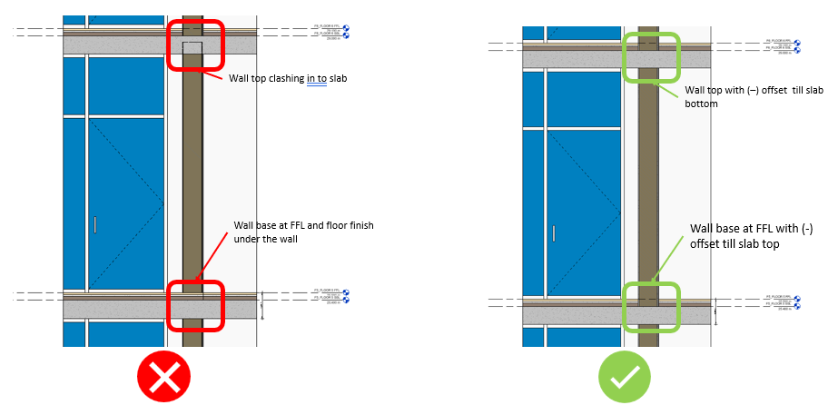
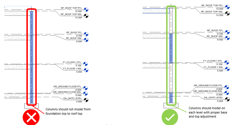
Walls and columns (including curtainwalls and façade elements) shall be modelled and hosted at their corresponding building levels. This enables accurate calculation of footprint areas for BUA, GA, and GFA.
Model elements from linked discipline models shall not clash with elements within the active model. Proper interdisciplinary coordination and clash detection shall be performed throughout the modelling process, and all identified clashes shall be resolved prior to IFC export and submission.
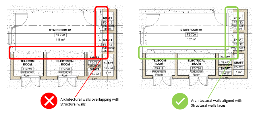
SLABS
Slabs are essential building elements within the BIM model and play a critical role in representing floor systems, structural load transfer, spatial separation, and level-based area calculations. Proper slab modelling is important to maintain structural coordination, correct room bounding behavior, and accurate automated compliance calculations within the BIM E-Submission Platform.
All slabs shall be modelled using the appropriate floor or slab creation tools available within the BIM authoring software.
Slabs shall be properly connected and coordinated with surrounding walls, columns, and bounding elements to ensure model integrity and accurate Space/Room enclosure.
Structural slabs shall be modelled and exported exclusively from the Structural model. Architectural floor finishes, floor toppings, screeds, and floor tile build-ups shall be modelled within the Architectural model only.
Structural slabs shall be hosted to the Structural Slab Level (SSL), while architectural floor finishes shall be hosted to the Finished Floor Level (FFL)
Slab elements shall not be duplicated across multiple discipline models, and it shall be ensured that there are no overlaps or clashes between structural slab and finishes.
Structural slabs shall be exported to IFC as IfcSlab entities. Architectural floor finishes, floor coverings, and floor tile layers shall be exported as IfcCovering entities with the appropriate PredefinedType assigned.
Each slab element shall be correctly hosted to its corresponding Building Storey to ensure proper IFC hierarchy, level-based coordination, and accurate area calculations.
Expansion joints shall be represented within the BIM model as physical separations between adjacent slab elements. Separate slab sketches shall be maintained on either side of the expansion joint, and slab geometries shall not overlap across the joint location.
PARKING
Parking areas represent designated spaces within a building or site used for vehicle parking or storage. All parking spaces shall be modelled and included in the IFC export. Parking bays shall be exported as IfcSpace entities.
Each parking bay shall be represented as a clearly defined model element with appropriate geometric representation.
Parking bays in the IFC model shall:
Be correctly hosted to their corresponding building levels
Not clash with other model elements
Be modelled with appropriate dimensions, including outer extrusion, wheel stops and other relevant physical elements shall be included where required by design
For tandem parking arrangements, the two dependent parking spaces shall be modelled and considered as a single parking bay, rather than separate individual parking entities
Parking bays located outside the building footprint shall be hosted to the GA_GATE LEVEL to ensure correct georeferencing and alignment within the BIM model.
The total number of parking bays modelled per level is used for the automatic generation of the Building Card summary within the BIM E-Submission Platform. These values will be cross-verified against the parking calculations submitted manually by the Consultant to the Authority. Therefore, it is essential that the total number of parking bays is accurately modelled and correctly assigned to their respective building storeys. Any discrepancy in quantity or incorrect level assignment may result in validation issues during the submission review process.
SPACES/ROOMS
Spaces/Rooms are mandatory elements within IFC models submitted to the BIM E-Submission Platform. The information associated with Spaces/Rooms plays a critical role in automated compliance checking and is used for the calculation and verification of parameters, including Gross Floor Area (GFA), Built-Up Area (BUA), and Gross Area (GA).
All Spaces/Rooms shall be modelled as properly bounded areas or volumes using the dedicated Space/Room creation functionality available within the BIM authoring software and exported to IFC as IfcSpace entities.
Each functional area, non-functional and accessible Roof/Terrace within the building shall be represented by a single corresponding Space/Room element.
GEOMETRY RULES AND CONSTRAINTS
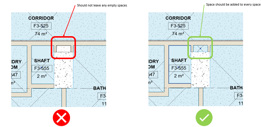
- All areas, including voids, shafts, inaccessible zones, and non-usable spaces, shall be modelled using dedicated Space/Room elements where applicable.
- All Space/Room geometries shall be properly enclosed using model elements or room separator lines. Where architectural or model elements are already defining the room boundaries, excessive use of room separators should be avoided, as unnecessary separator elements may increase model size and negatively impact model performance.
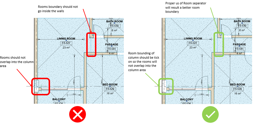
Where linked models are used to define room boundaries, the Room Bounding option shall be enabled for the linked models. In addition, overly complex room geometries should be avoided, as irregular room shapes may result in export issues or displaced geometry within the IFC model.
Spaces/Rooms shall not overlap and each spatial area within the model shall be represented only by a single corresponding Space/Room element. Redundant and duplicate Space/Room shall be removed prior to IFC export.
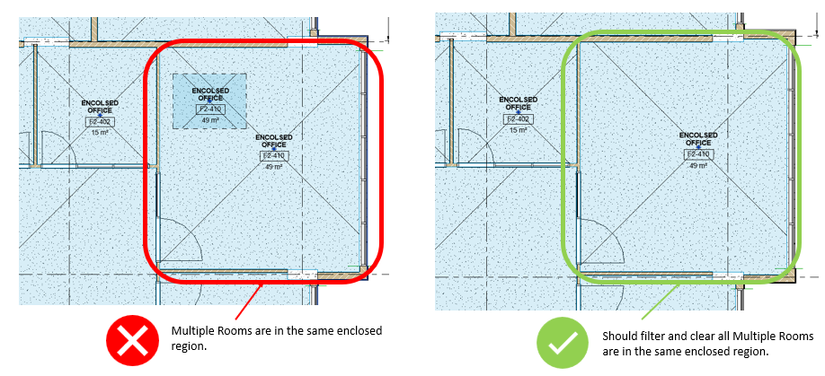
Spaces/Rooms should be modelled on a level-by-level basis to support accurate area calculations during automated compliance checking.
Double-height or multi-height spaces may be maintained as single Space/Room elements extending across the full height of the space and do not require splitting at each level.
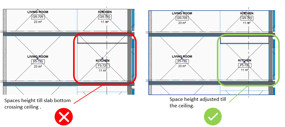
Service shafts and similar vertical spaces shall be modelled separately for each level. Where ceilings are present, the upper limit of the Space/Room shall extend up to the lowest point of the ceiling. In areas without ceilings, the room height shall extend up to the slab soffit level.
MODEL SEGREGATION
GENERAL PRINCIPLES
BIM models developed using authoring tools may be divided into multiple IFC models for submission where required. Model segregation applies to IFC deliverables only and does not restrict how models are developed within BIM authoring tools.
All submitted IFC models shall comply with the requirements defined in the Dubai BIM Standard and this document, regardless of how the native BIM models are structured. Model splitting shall ensure:
No duplication/missing of elements across IFC files
Consistent attribute information across related models
Correct assignment of BuildingNum and BuildingPartNum attributes
DISCIPLINE SEGREGATION
BIM models shall be segregated by discipline for submission unless it is agreed otherwise with the permitting team. Architectural and Structural models shall be developed and exported as separate IFC models to ensure clarity, coordination, and proper allocation of responsibility.
SEGREGATION STRATEGY
The BIM model shall be organised and, where required, split into multiple IFC files in accordance with the following principles:
Single Building: For standalone buildings, separate IFC models shall be submitted for each discipline (e.g. Architectural and Structural).
Multiple Towers with Shared Podium: Where multiple towers share a common podium or basement:
podium and basement shall be developed and exported as a separate model
Each tower shall be developed and exported as an independent model.
Multiple Buildings within a Parcel: Where a project includes multiple buildings within a single parcel, each building shall be developed and submitted as a separate BIM model and IFC file.
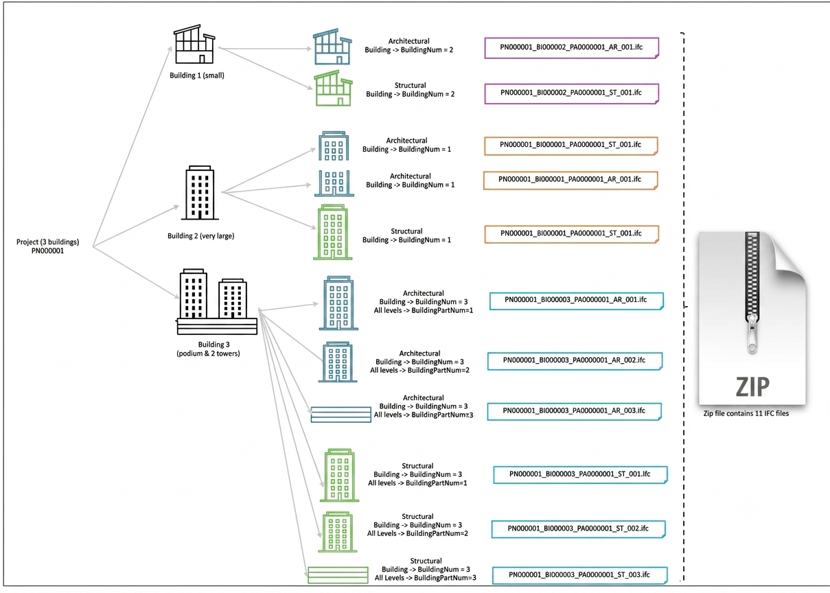
Figure 2 illustrates a hypothetical project with three building configurations. The corresponding IFC deliverables may be structured as follows:
Table 4. IFC deliverables
| Building | Description | Submitted IFC files |
|---|---|---|
| Building 1 | Small standalone building | Two IFC models (Architectural and Structural) |
| Building 2 | Single tower | Two IFC models (Architectural and Structural). For large models, the Architectural model may be split into multiple IFC files |
| Building 3 | Multiple towers sharing a common podium | Six IFC models. Each tower and the podium should be treated as separate models. When a building is divided into multiple parts, the BuildingPartNum property should be assigned accordingly |
The BuildingPartNum attribute used to identify building parts within the IFC model shall not be confused with file-based model splitting used due to file size or complexity constraints. Refer to the Dubai BIM Standard (File Naming section) for detail.
MODEL GEOREFERENCING
All BIM models submitted to the BIM E-Submission Platform shall include valid and accurate georeferencing information.
Georeferencing shall ensure that the model is correctly aligned in the X, Y, and Z directions with the approved project location and elevation data.
Incorrect or missing georeferencing may result in submission validation errors or incorrect spatial alignment within the platform.
COORDINATES & DMD LEVEL
It is the responsibility of the Model Author to ensure that the BIM model is correctly georeferenced using the correct project location and Gate Level elevation.
The following procedure may be used to obtain and apply the required georeferencing data:
Log in to the Build in Dubai portal and navigate to “My BIM Sessions”.
Start a new session and enter the Parcel ID in the plot number field.

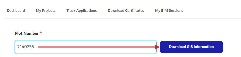
Download the GIS information provided for the selected parcel.
Extract the downloaded file and open the DXF file named “PARCELS.
Set the units to meters and save the file as a DWG.
Import the DWG into the BIM authoring tool to establish project coordinates.
The official DMD (Dubai Municipality Datum) elevation is specified in the setting-out plan.
The X, Y, and Z for the IfcSite element in the IFC model shall reflect the real and correct location of the IFC model on the map so it is correctly displayed in Dubai Digital Twin Platform.
MODEL COORDINATION & CLASH DETECTION
All models developed using BIM authoring tools shall be properly coordinated prior to submission to the BIM E-Submission Platform.
Although the current submission requirements mandate only Architectural and Structural models, coordination shall be performed across all relevant disciplines, including Architecture, Structure, MEP, Façade, Interior Design, and Landscape. This ensures the development of an integrated and consistent Information Model and helps minimize design conflicts and construction issues.
SUBMISSION SELF-ASSESSMENT
INTRODUCTION
After exporting the BIM model to IFC format, each IFC file shall be thoroughly reviewed prior to uploading it to a BIM session within the Build in Dubai (BID) platform. Performing a self-assessment before submission helps identify modelling issues, missing information, classification errors, and coordination problems at an early stage, thereby reducing validation failures during the authority review process.
To effectively review IFC models, BIM Authors are expected to have a basic understanding of the IFC4 schema and IFC model structure. You can visit the IFC4 documentation page to learn about IFC elements, their property sets, and their properties. Once you understand these basics, you will be able to review IFC models on your own.
MODEL GEOMETRY / VISUALIZATION QUALITY
The overall geometry and visual representation of the IFC model should be reviewed using an IFC viewer prior to submission. Any IFC viewer may be used for this review process based on user preference. IFC viewers commonly used include: BIMCollab Zoom, BIM Vision, and Open IFC Viewer.
MODEL INFORMATION QUALITY
Information quality is one of the most critical aspects of the BIM workflow. The effectiveness of automated compliance checking depends heavily on the accuracy and completeness of the information embedded within the BIM model.
With reference to the requirements defined within Appendix B – Model Attribute Matrix, it shall be ensured that all mandatory attributes are properly populated for the corresponding model elements prior to submission.
To assess information quality, the following desktop tools may be used:
QA/QC Checker: for checking the completeness, correctness, and validity of element information (Download Link).
Building Card Generator: for generating the building card and verifying spaces/rooms information (Download Link).
While the E-BIM Submission Platform can be used for model validation, desktop tools are typically more efficient for early identification of issues within the submission. However, the E-BIM Submission Platform shall still be used for final validation, including checking for compliance with the Dubai Building Code and verifying georeferencing correctness.
MODEL SELF-ASSESSMENT (OFFLINE)
The offline self-assessment of IFC models may be carried out using any IFC viewer together with the desktop applications provided by Dubai Municipality. In this section, the offline checking is demonstrated using the BIMcollab Zoom application. While performing the offline assessment, it is recommended to load all IFC models associated with the project, including all buildings and all discipline models, within the same review session to ensure accurate coordination, clash detection, level consistency, and information validation results. A detailed explanation of the checks is provided below.
NAMING CONVENTIONS
It shall be verified that all IfcBuildingStorey elements:
Aligned with the building design levels,
Match the corresponding levels shown in 2D drawings
Level names comply with the Dubai BIM Standard naming convention requirements
Additional checks shall ensure that:
No dummy or reference levels are exported
All models (Architectural, Structural, etc.) use identical level structures
An IFC viewer can be used to verify level names and compare them with the corresponding 2D drawings. The QA/QC Checker tool will also report a Critical issue if any level name does not comply with the requirements.
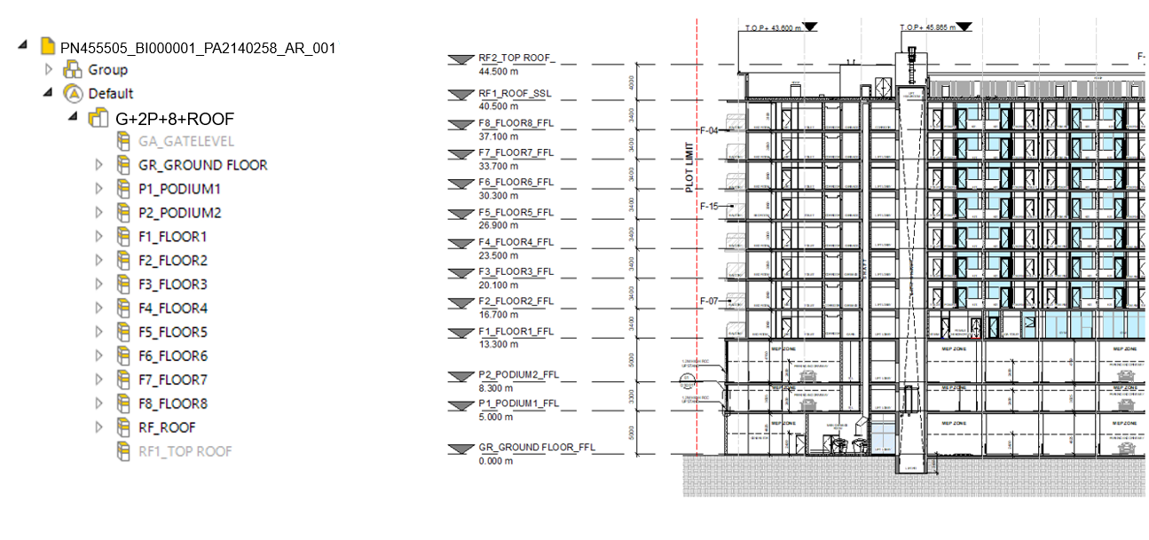

Figure 4. Issue in level names in results of QA\QC validation.
MODEL GEOLOCATION & GATE LEVEL.
It shall be ensured that all IFC files are correctly geo-referenced in the X, Y, and Z directions prior to the final submission. Verification steps:
Check IfcSite coordinates (X, Y, Z) in an IFC viewer. For Revit users, these coordinate values shall correspond with the Internal Origin coordinates. Matching coordinate values confirm that the IFC model has been exported using the correct geolocation settings
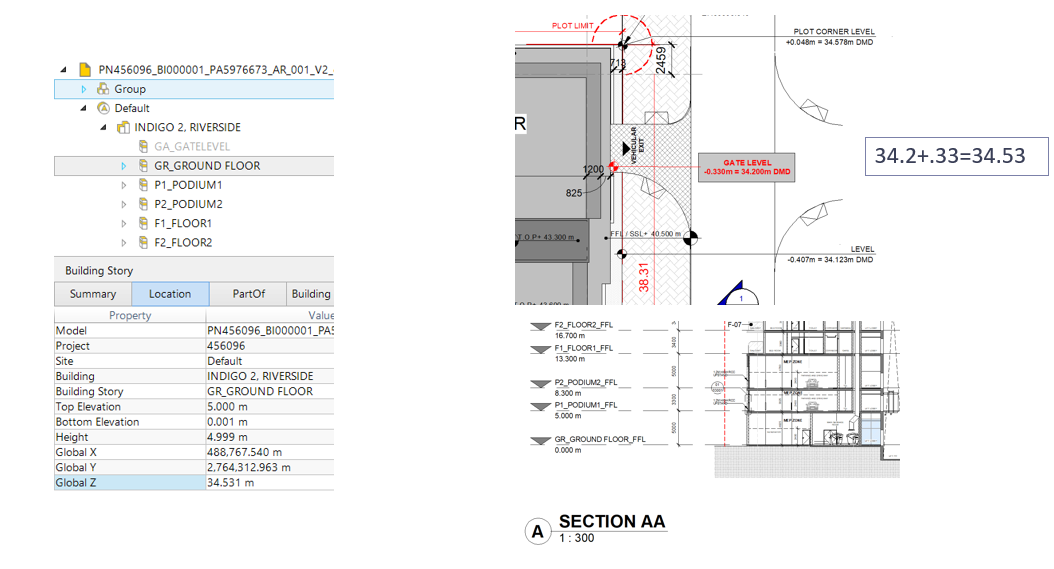
Based on your project zero-elevation level, verify that the GA_GATE LEVEL or GR_GROUND Level matches the official DMD (Dubai Municipality Datum) elevation specified in the setting-out plan.
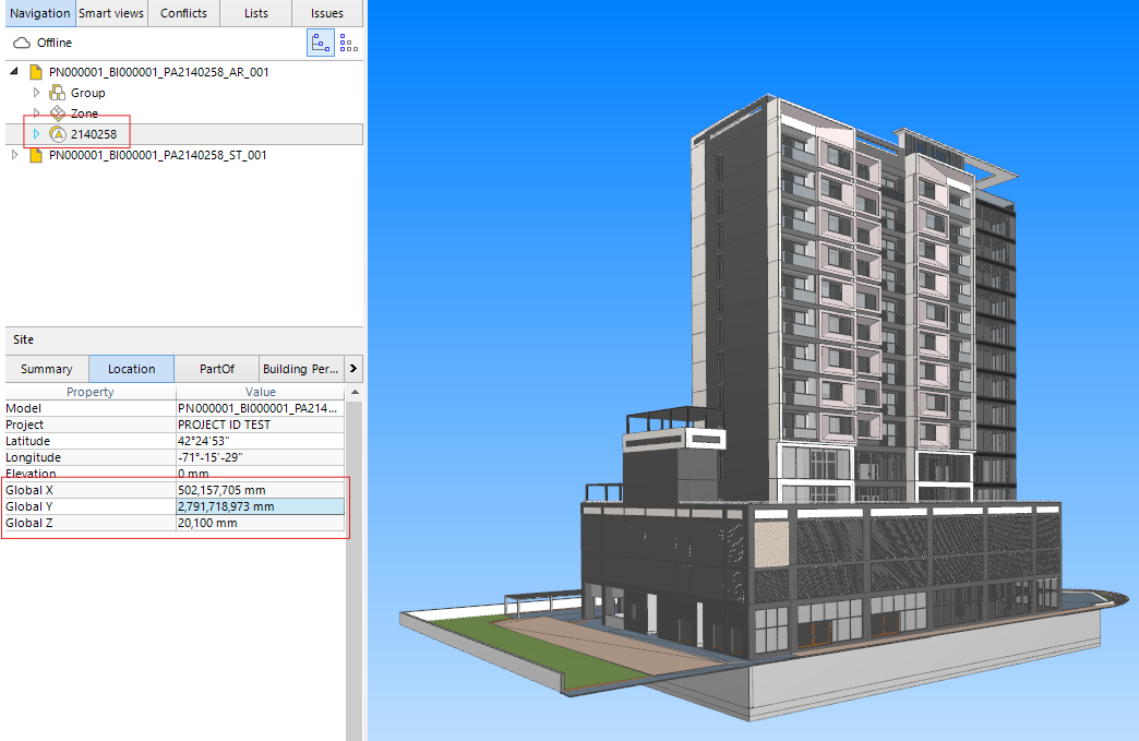
Figure 5. Using BIMcollab ZOOM to check IfcSite coordinates
MODEL GEOMETRY/VISUALIZATION
The IFC model geometry/visualization shall be reviewed to ensure:
Elements are exported to the correct IFC classes
No elements are floating or incorrectly hosted
No elements are placed outside their intended Building Storey
No missing, duplicated, or incomplete geometry exists
Elements serve their visual purpose
Additional requirements:
All spaces (IfcSpace) shall be present for internal areas, accessible roofs, and terraces
Elements spanning multiple levels shall be reviewed and split where required
Material appearance shall reflect the approved design
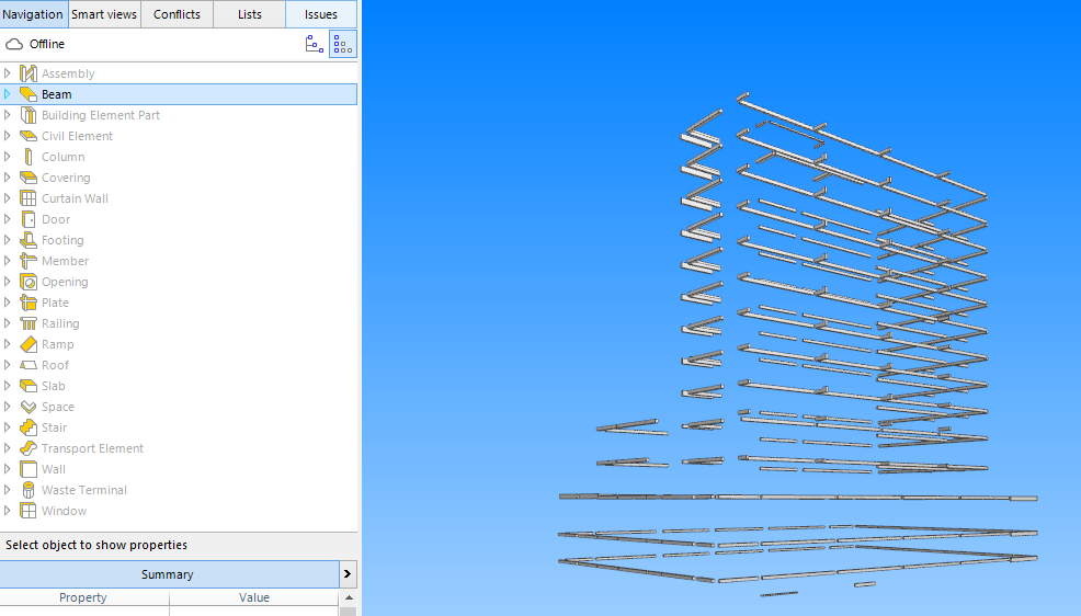
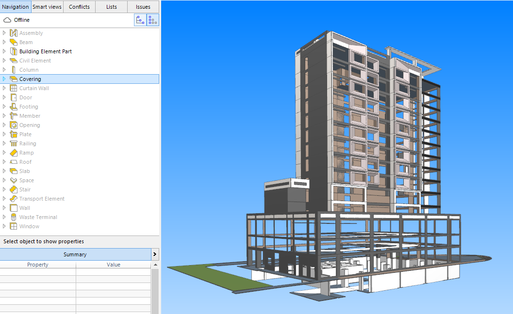
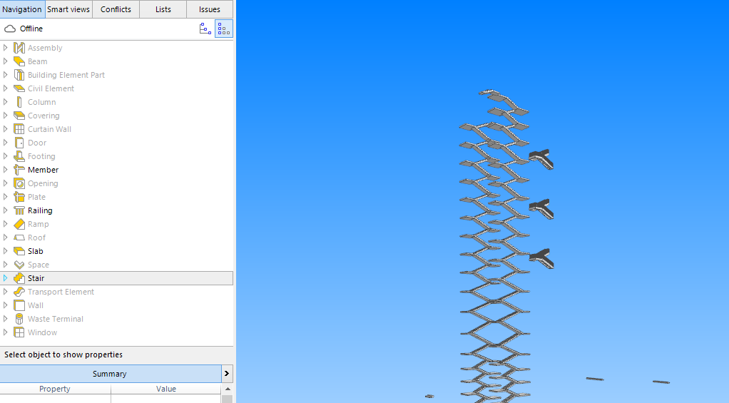
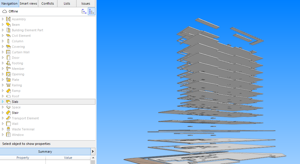
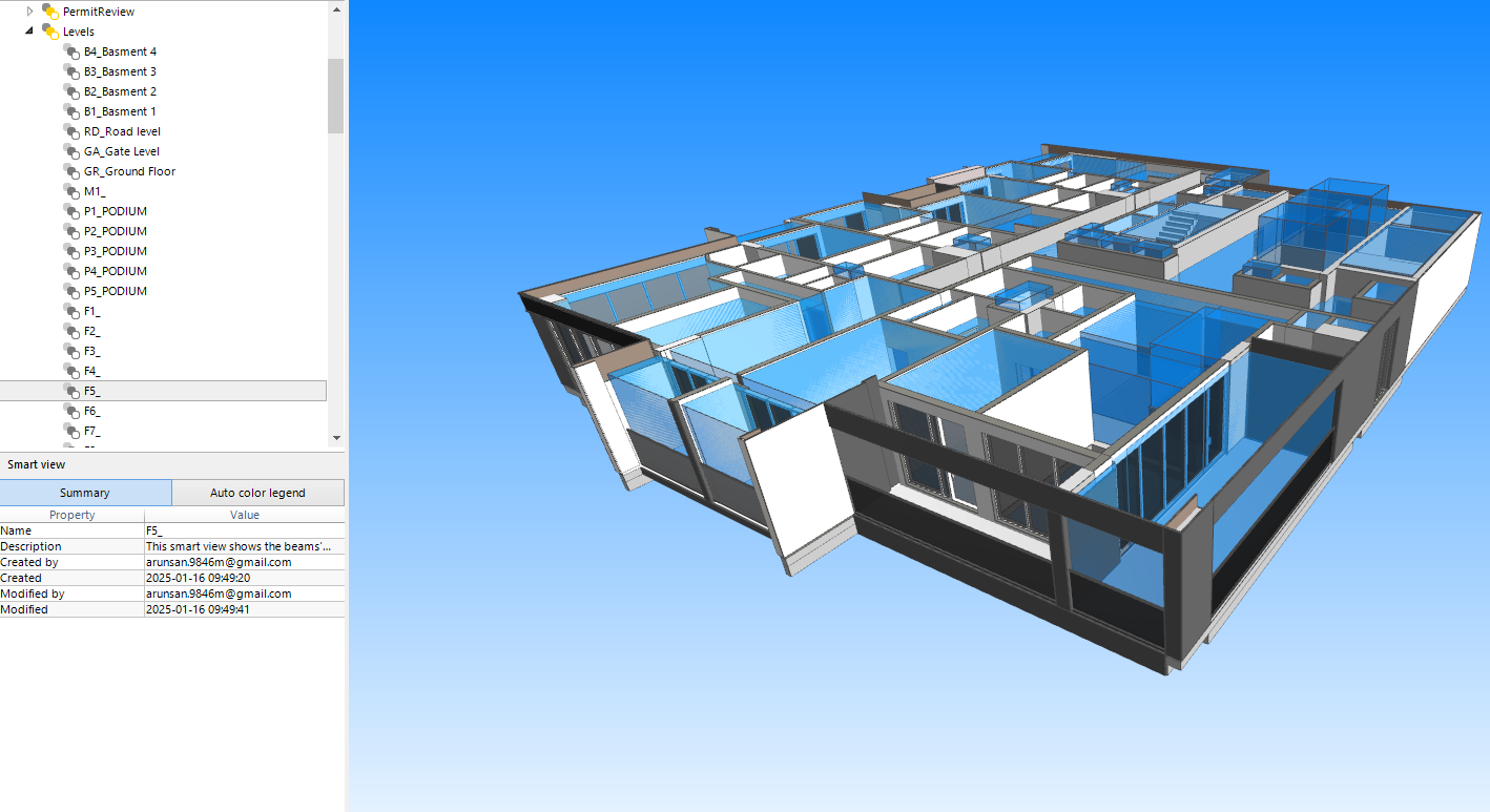
To perform the above verifications, an IFC viewer may be used along with its filtering and element isolation features to inspect the model and its components.
The screenshots below illustrate examples of filtered views created for visual inspection.
GENERAL INFORMATION ISSUES (QA/QC)
The information quality of the IFC model shall be check against the requirements specified in the DM BIM Standard and defined in Appendix B – Model Attribute Matrix using the QA/QC tool using the desktop or online tool.
Verification steps:
Download the QA/QC desktop tool from the download link on Section 3.1.2.
Extract the files inside the downloaded ZIP file on a local folder (no installation or admin rights are required to run the app)
Double-click on the application to run (Figure 7)
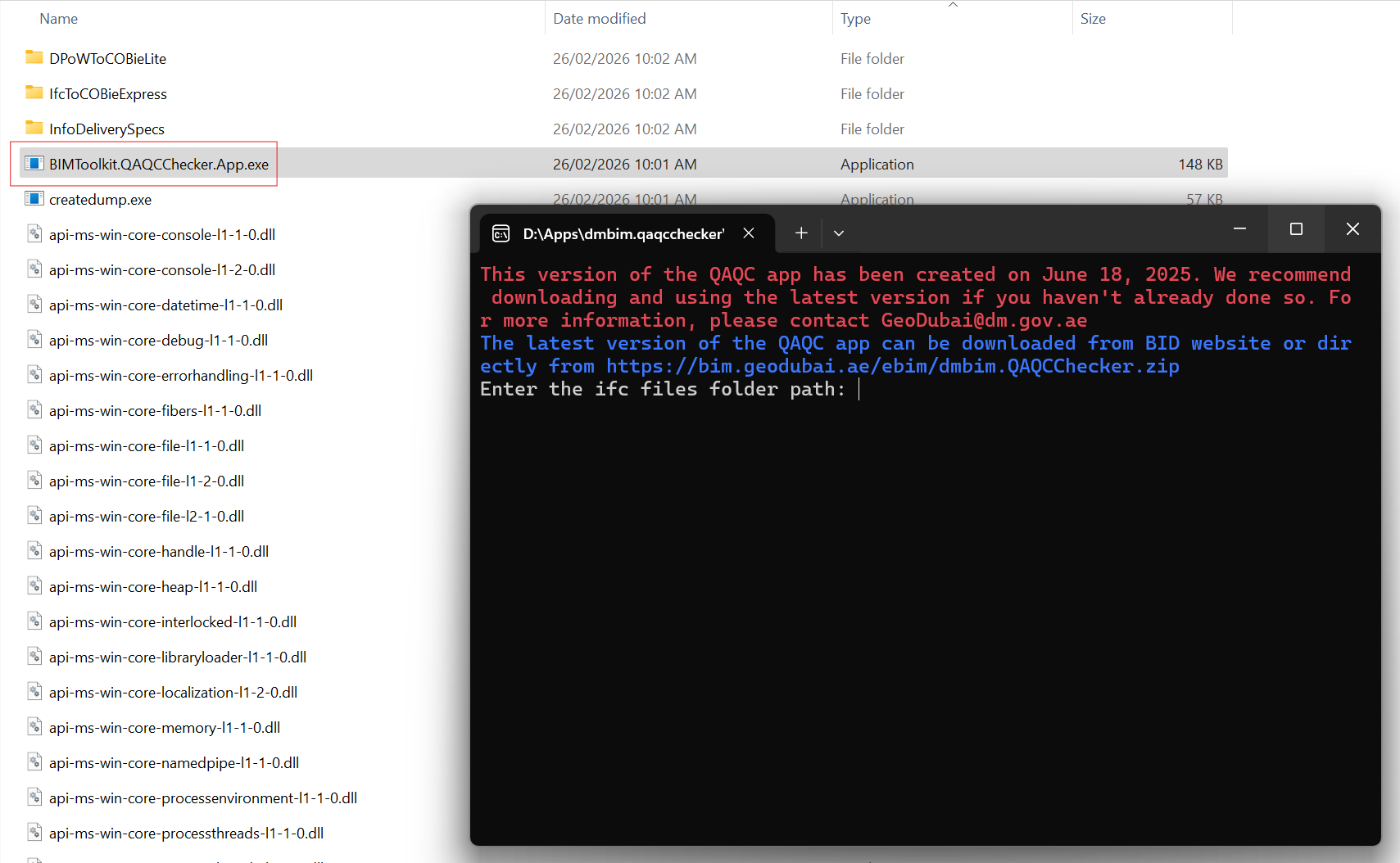
[]{#_Ref229651632 .anchor}Figure 7. QA\QC application
- Make sure all IFC files are in a single folder (preferably on the local drive) and then enter the folder path into the console application and press enter.
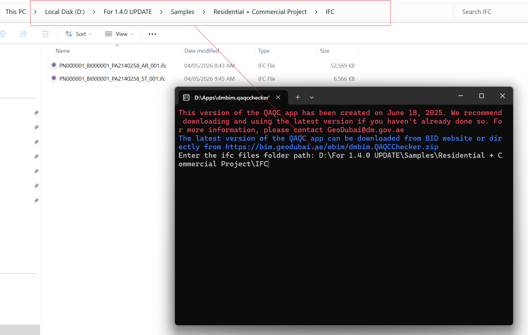
- Once the QA/QC application completes the validation process, the application window will close automatically, and the QA/QC results will be saved in a csv file inside the same folder.
READING QA/QC RESULTS
Each row in the results (Figure 9) represents an issue related to an element or an element type. If the issue is related to a single element, EntityID will be shown. If the issue is related to an element type, the EntityID cell for that row will display “-1”.
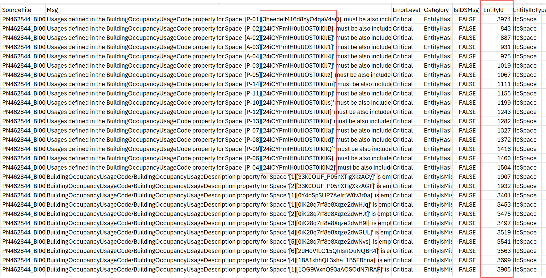
The QA/QC results are classified into three categories:
Critical: Must be resolved for submission approval
Errors: Non-critical issues that should be corrected
Warnings: Low-priority issues with recommendation to review and address where feasible
Critical issues relate to essential information required for rule checking and Building Card generation. Therefore, all critical issues shall be resolved prior to submission approval. Errors are also important and should be resolved before final submission.
To identify affected elements within an IFC viewer or the native BIM software, users may refer to the GUID and Element ID provided in the QA/QC results.
SPACES/UNITS USAGE INFORMATION (BUILDING CARD)
IfcSpace (Room) information is a critical component of the BIM model and contains a significant portion of the project data required for submission. This information is used by the Building Card generation process to support automated calculations and validation.
The Building Card includes, but is not limited to:
Area calculations (e.g. BUA, GFA, GA)
Unit definitions and grouping
Parking information
Space-level attributes and classifications
The Building Card Generator application may be used locally to generate a summary of the project data extracted from IfcSpace elements. Upon generation, the results shall be reviewed to ensure:
Accuracy of calculated areas
Completeness of Space/Room information
Correct assignment and grouping of units
Consistency with submitted design calculations
Verification steps:
Downloaded the Building Card Generator desktop tool from the download link on Section 3.1.2
Extract the files inside the downloaded ZIP file on a local folder (no installation or admin rights are required to run the app)
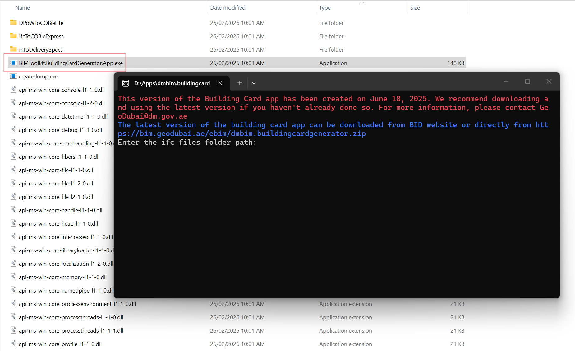
Double-click on the application to run (Figure 10)
- Make sure all IFC files are in a single folder (preferably on the local drive) and then enter the folder path into the console application and press enter.
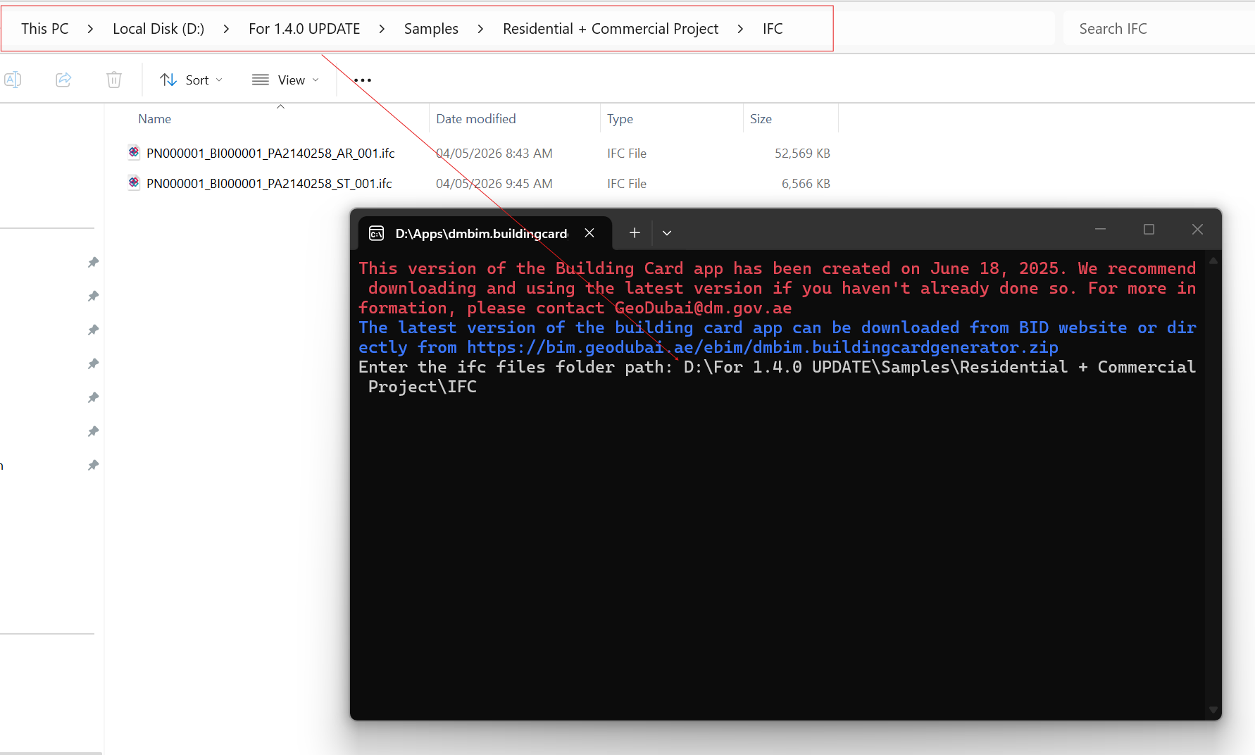
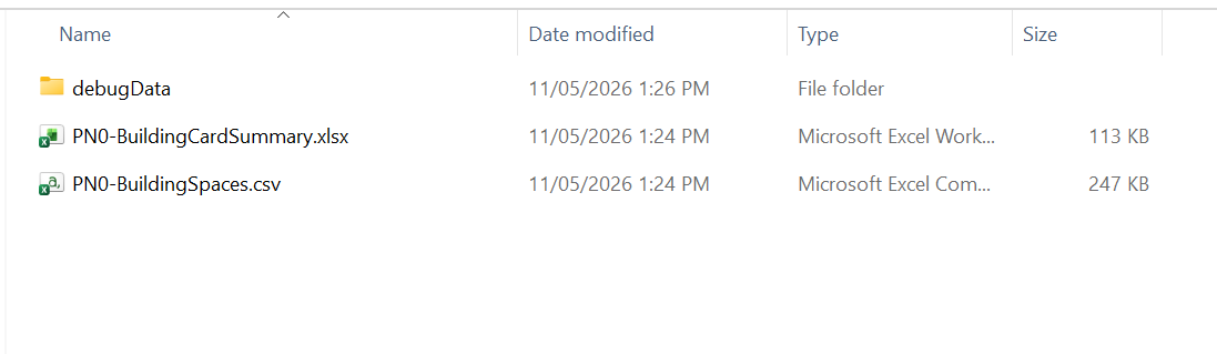
Once the application completes the generation process, the application window will close automatically, and a folder named “temp” will appear in the folder.
Extract the zip file inside the “temp” folder for the generated building card and related files.
READING BUILDING CARD RESULTS
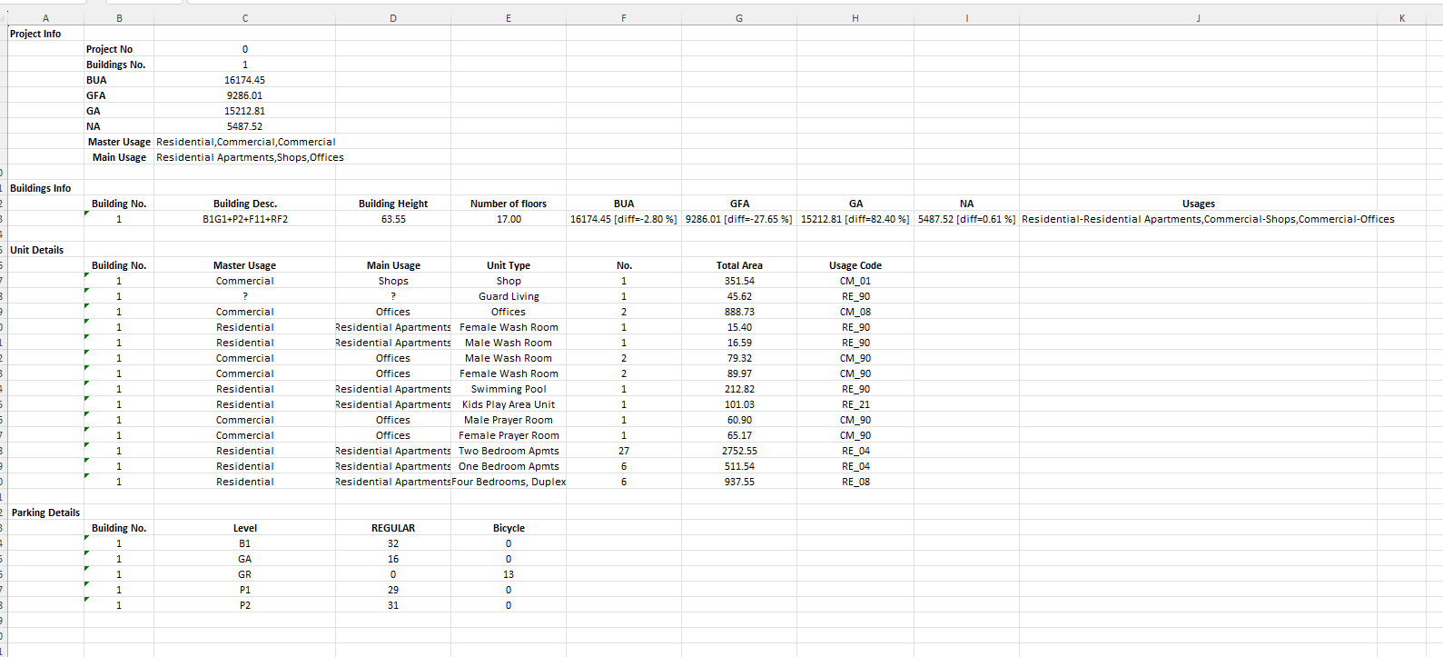
- The BuildingCardSummary.xlsx File
This file is the main output data file, which contains the collected and processed data. The file contains a Summary sheet and other sheets that show the breakdown of the results displayed on the Summary sheet.
Some cells in the file that display aggregated values contain hyperlinks to other sheets, allowing users to locate the corresponding source data.
The Summary Tab:
The following describes the current structure of the Building Card Summary:
Project Info: The first section of the page displays the general Project Info, such as the Project Number, number of buildings, total BUA/GFA/GA/NA, and other related information.
Building Info: The second section displays the Building Info, including the number of floors for each building, building height, and the differences between manually calculated areas and automatically calculated areas.
Unit Details: The third section presents the Unit Details like occupied units and the common facilities within the project.
Parking Details: The fourth section displays the parking details, including the number of parking bays on each level.
The summary values should be verified against the submitted calculation drawings. If any discrepancies are identified, the root cause must be determined and corrected. Any deviation between manual and automated values shall not exceed ±5%, unless justified by design conditions.
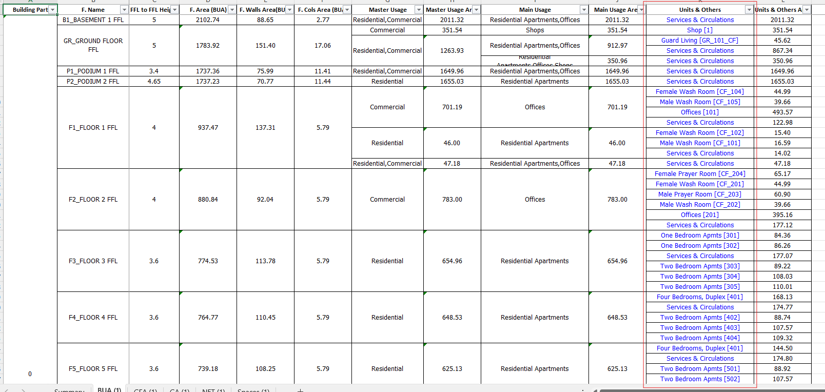
- BUA, NA, GFA, Spaces Tabs:
In the other sheets of the Building Card Summary file, units are grouped under the Master Usage and Main Usage categories of the building, and the area of each Master Usage and Main Usage category is displayed for every level. Clicking on a unit will navigate to the Spaces sheet to show the spaces of the selected unit.
- Debugging Files
Besides the main file, the application generates a set of supplementary files located in the “DebugData” folder to assist users in diagnosing issues related to unexpected results in the main file.
For example, if the automatic area is not generated in the Building Card Summary and a value of “-1” is displayed, this indicates that some required data is missing from the IfcSpace information. In such cases, the Spaces.csv file can be used to identify the root cause of the issue. If missing information is identified within the IfcSpace data, users should check the Issues Column (Column AF) and locate the entries that refer to IfcSpace elements with incomplete or missing attributes.
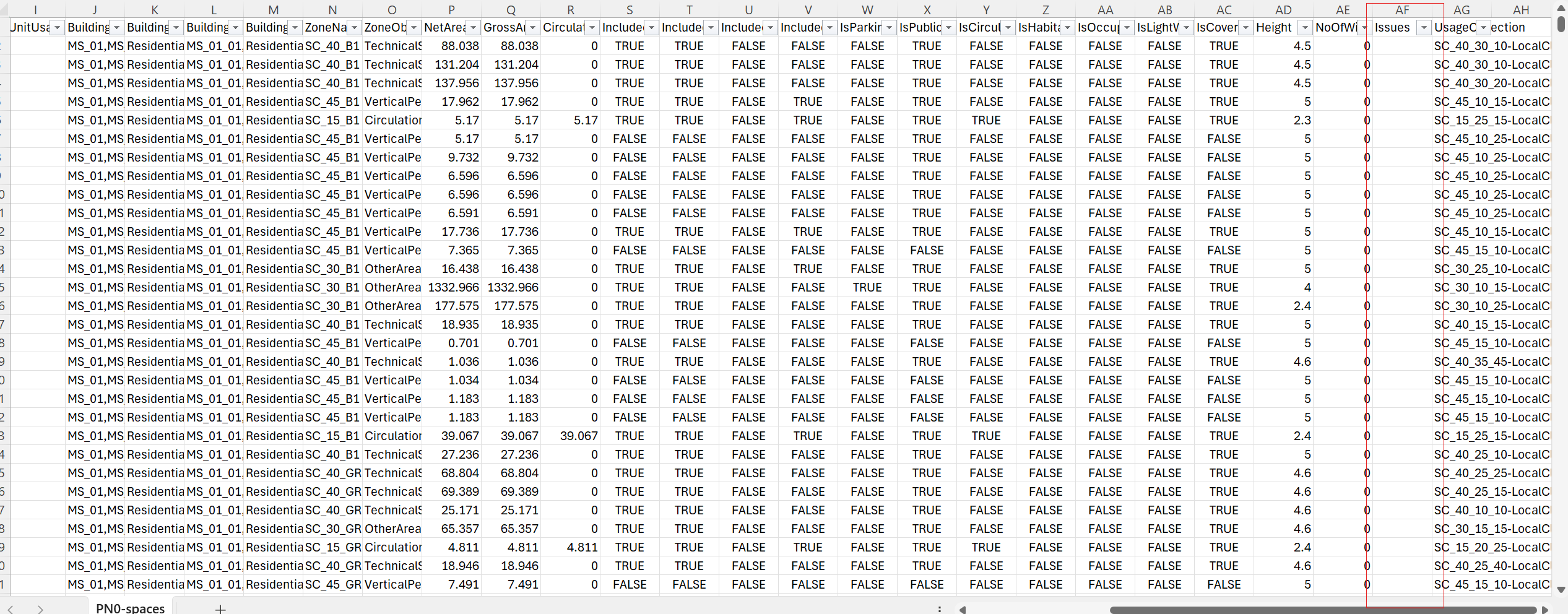
When the automated area calculation shows a deviation exceeding ±5% compared to the manual area values, the Storeys.csv file may help in identifying the root cause of the issue.
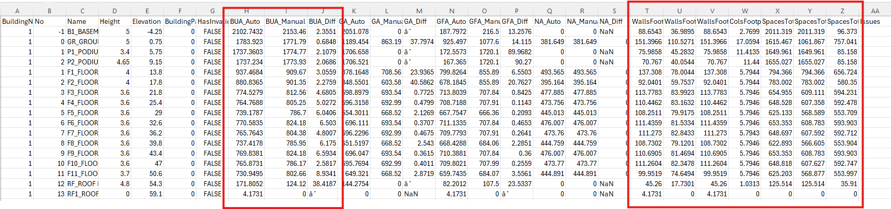
The Storeys.csv file lists all the model storeys, where:
Column H displays the automated area.
Column I displays the manual area.
Column J displays the difference between the automated and manual areas.
In case of any area deviation, users can identify the level with the largest area difference, then review Columns T to Z, which contain the areas of walls, columns, and spaces. The area for each area type can be reviewed to determine the source of the discrepancy. The additional csv files can be used to further narrow down the root cause of the area deviation.
MODEL SELF-ASSESSMENT (ONLINE)
Online self-assessment shall be performed after uploading the IFC files to a BIM session on the Build in Dubai (BID) platform.
The platform provides automated validation tools to verify compliance with BIM submission requirements and regulatory checks.
Prior to uploading the IFC files, the following requirements shall be verified:
The IFC model units shall be set to meters
The IFC schema shall be IFC4 Reference View
The IFC structure shall be IfcProject → IfcSite → IfcBuilding → IfcBuildingStorey(s)
IFC and zip filenames shall comply with the Dubai BIM Standard naming convention
The total ZIP file size shall not exceed 150 MB, unless otherwise specified by the platform
Once the files are uploaded, the platform will automatically perform validation, including:
QA/QC checks for model information completeness and correctness
Building Card generation based on Space/Room data
Geolocation validation to verify model placement on the map
Compliance (Rule) checking against Dubai Building Code requirements
Users shall review all validation results and ensure that:
No Critical issues remain unresolved
Identified Errors are corrected prior to submission
Any discrepancies in Building Card results are investigated and resolved
GENERAL INFORMATION ISSUES (QA/QC)
The QA/QC results generated within the BIM platform replicate the results produced by the desktop QA/QC application and shall be reviewed as part of the online validation process. To access the QA/QC results within the platform, users can navigate to the QA/QC tab, select Load Data to display the validation results. Once the results are displayed, the QA\QC issues can be reviewed or downloaded.
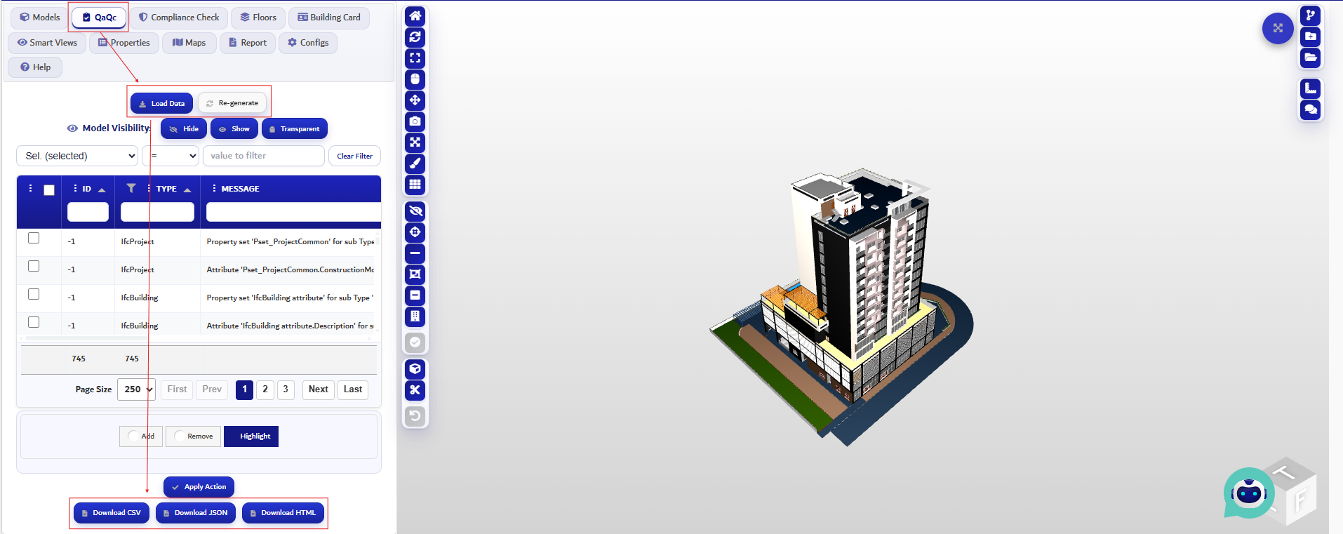
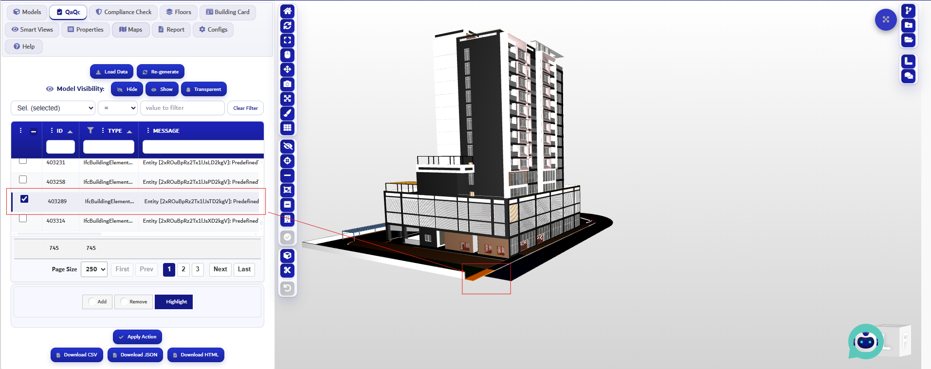
One advantage of using the online QA/QC system is the ability to use the tick box in the report table to highlight the element in the 3D view. By selecting an issue in the report, the corresponding element can be highlighted in the viewer, allowing faster identification and resolution.
SPACES/UNITS USAGE INFORMATION (BUILDING CARD)
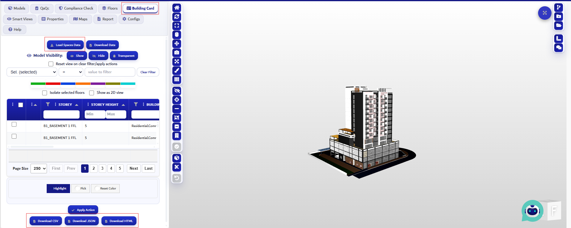
The Building Card results generated within the BIM platform replicate those produced by the desktop Building Card Generator and shall be reviewed as part of the online validation process. To access the Building Card results within the platform, users can navigate to the Building Card tab and select Load Space Data to generate and display the results. Once the results are loaded, the space information can be reviewed or downloaded.
MODEL GEOLOCATION CHECK IN BID BIM VIEWER
The BIM model shall be verified for correct geolocation within the Build in Dubai (BID) BIM Viewer as part of the online validation process.
To perform the geolocation check:
Navigate to the Maps tab within the BIM Viewer
Select the View Setback option
Review the model placement relative to the parcel boundary displayed on the map
A correctly georeferenced model shall:
Align accurately with the designated parcel boundary
Be positioned correctly in the X and Y directions
Match the approved project location as defined by the Parcel ID
If the building footprint is displayed within the correct parcel boundary, this confirms that the model has been properly georeferenced horizontally. Where misalignment is observed, the model georeferencing shall be reviewed and corrected in the BIM authoring software prior to resubmission.

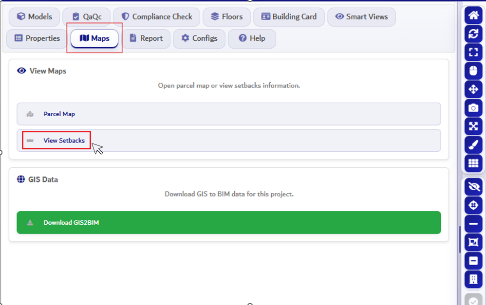
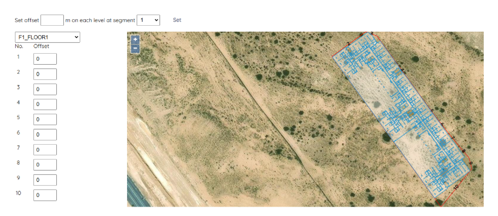
Figure 19. Building footprint
THE RULE CHECK (COMPLIANCE CHECK)
The Compliance Check against the Dubai Building Code is an essential component of the BIM E-Submission validation process. It enables automated verification of the BIM model against applicable requirements defined in the Dubai Building Code.
To review the rule-checking results within the BIM platform:
Navigate to the Compliance Check tab
Select Load Last Results to display the validation results
Review the list of rules and their corresponding status
Identify any failed rules and investigate the associated elements
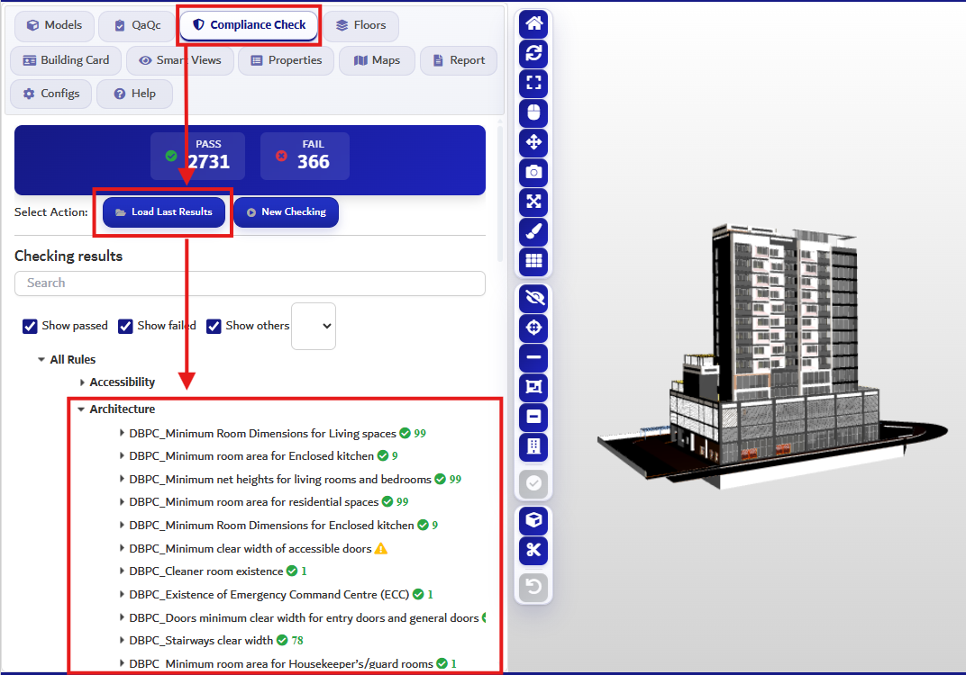
The platform allows users to isolate rule-checking results by level. To do this:
Select a specific rule from the results list
Isolate the affected elements
Choose the required level from the level selection dropdown
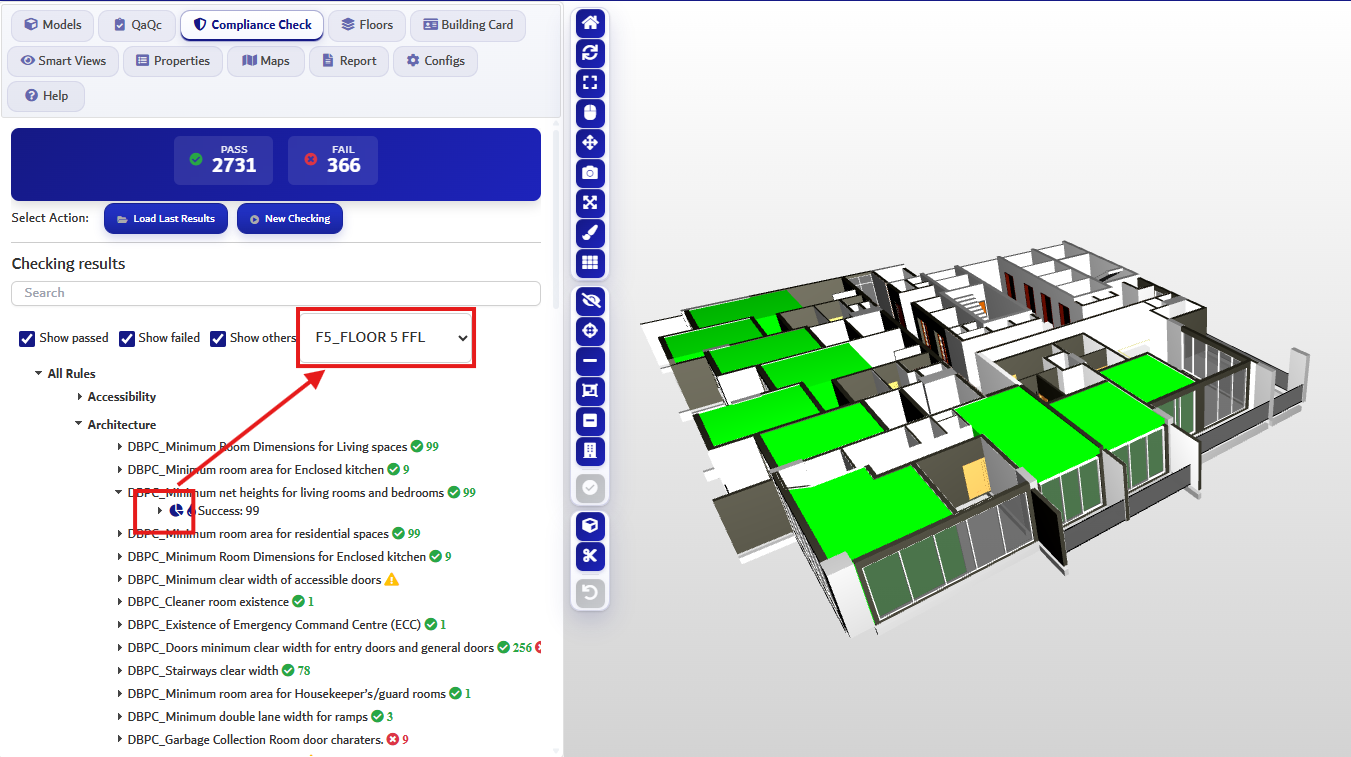
Failed rules shall be reviewed, and the building design shall be updated where required. In some cases, the system may flag rules as failed even when no actual violations exist (false positives). In such cases, the model may still be submitted for review by the Authority.
It is important to note that the accuracy of rule-checking results depends on the quality and completeness of the information embedded within the BIM model. Therefore, all QA/QC checks and Building Card validation shall be completed prior to running the compliance check.
FORMAL SUBMISSION
INTRODUCTION
All BIM submissions shall be formally completed through the building permit application process.
All IFC models shall be uploaded to a BIM Session within the Build in Dubai (BID) platform, and the BIM session shall be linked to the corresponding permit application.
Only models that have successfully completed the required self-assessment and validation procedures should proceed to formal submission.
UPLOAD SUBMISSION PACKAGE
After completing the self-assessment process, all IFC files shall be consolidated into a single zip file package prior to uploading.
Submission Preparation Requirements
All IFC files shall be verified to ensure compliance with the file naming conventions defined in the Dubai BIM Standard
IFC files shall be complete, validated, and free of critical issues
All required discipline models shall be included (as applicable)
The zip file size must not exceed the maximum allowed limit (currently 150 MB). For large projects where reducing the file size below the maximum allowed limit would compromise submission quality, an increased file size limit may be permitted upon approval
Creating the ZIP File
- Select all IFC files and use the standard operating system option Send to → Compressed (zipped) folder. The use of third-party compression software, such as WinRAR, is not recommended, as it may result in upload errors during the submission process.
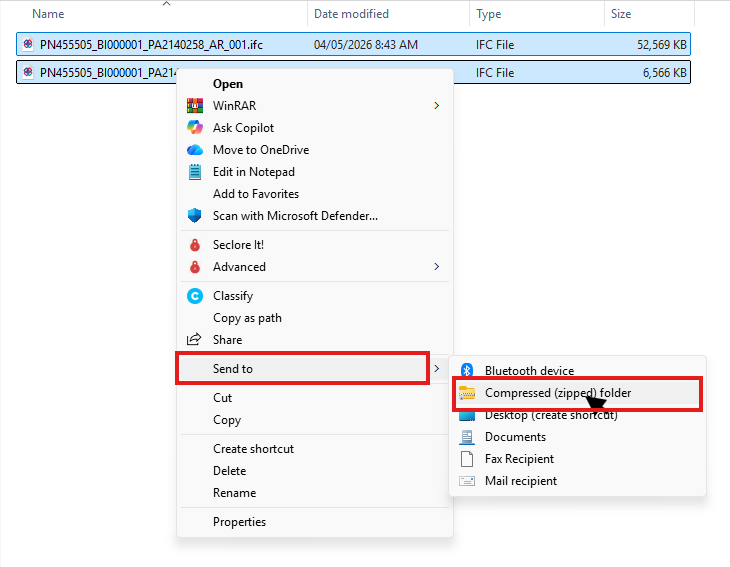
- After the zip file has been created, ensure that the zip file name complies with the Dubai BIM Standard naming conventions, the size of the zip file must not exceed 150 MB (subject to platform limitations).

Uploading to the BIM Session
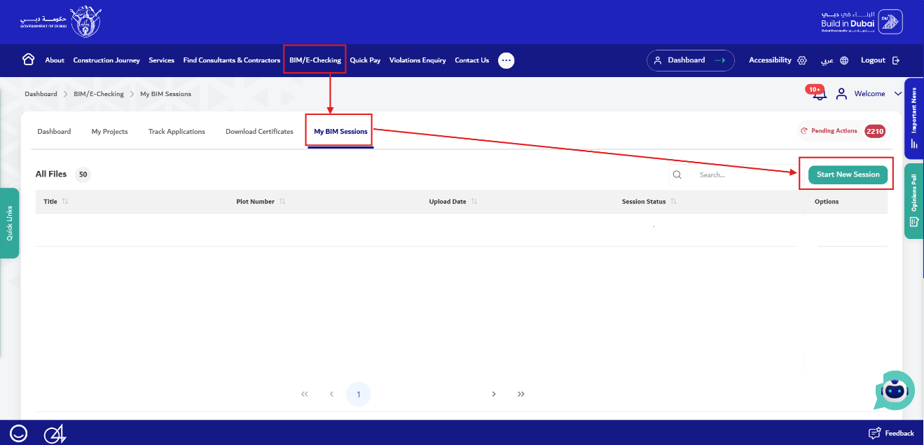
Log in to the Build in Dubai (BID) platform
Navigate to the BIM/E-Checking tab and select My BIM Session, then click Start New Session.
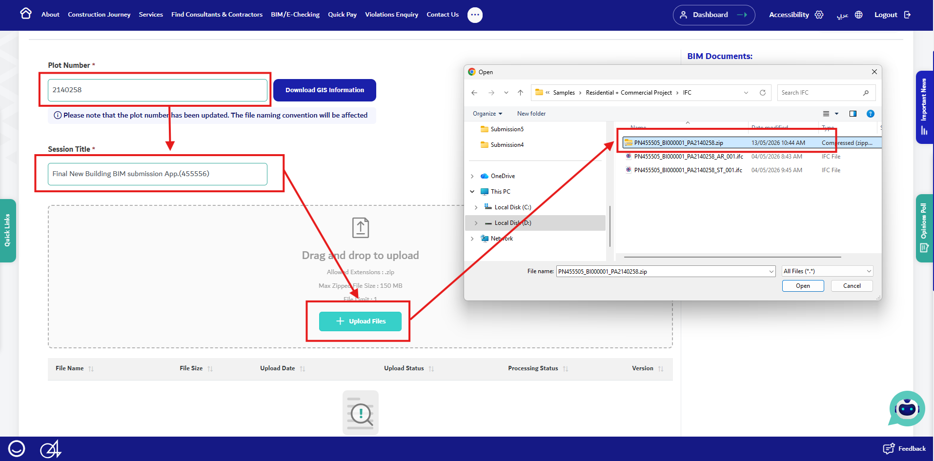
In the new session, enter the plot number and session title.
Upload the zip file using the Upload Files button, or by dragging and dropping the file into the designated upload area.
Processing and Validation
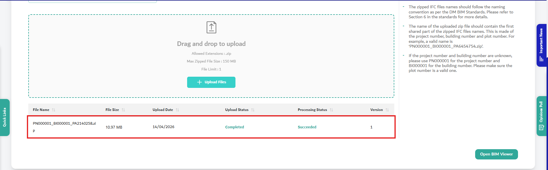
Once uploaded, the system will automatically process the submission package
Processing time may vary depending on file size and complexity
Upon successful processing, the BIM session becomes available for attachment to the permit application
Linking BIM Session to Permit Application
- Navigate to the application attachment section and Under the Drawings section, select BIM Session
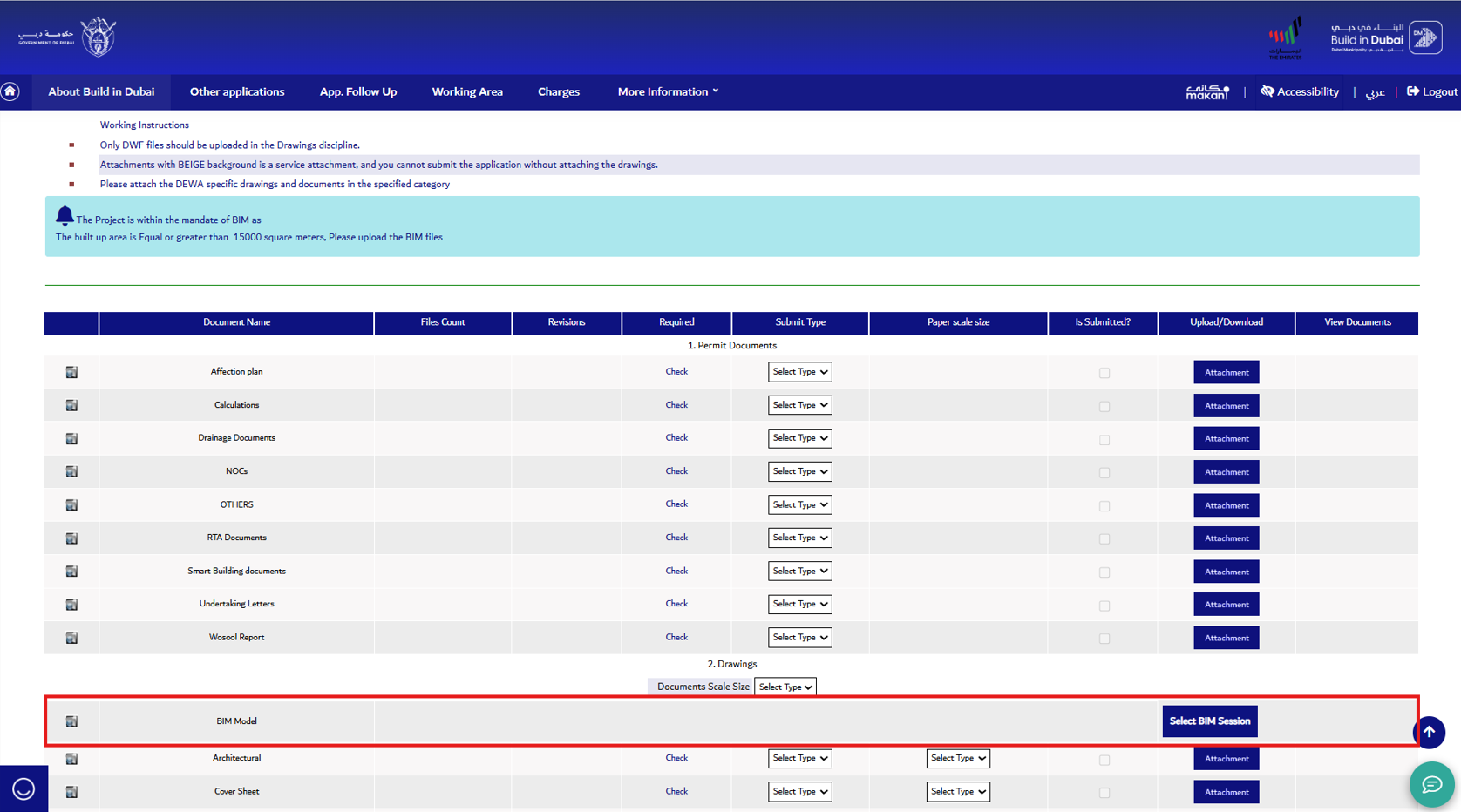
- Choose the relevant BIM session associated with the parcel and attach the selected BIM session to the permit application
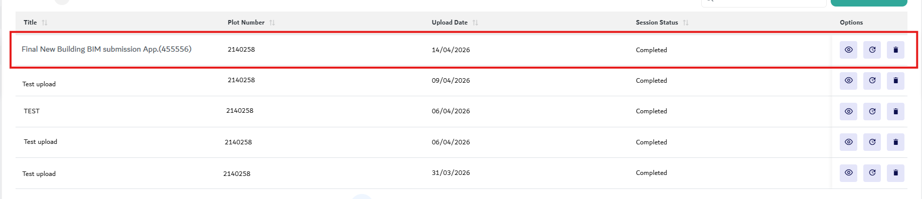
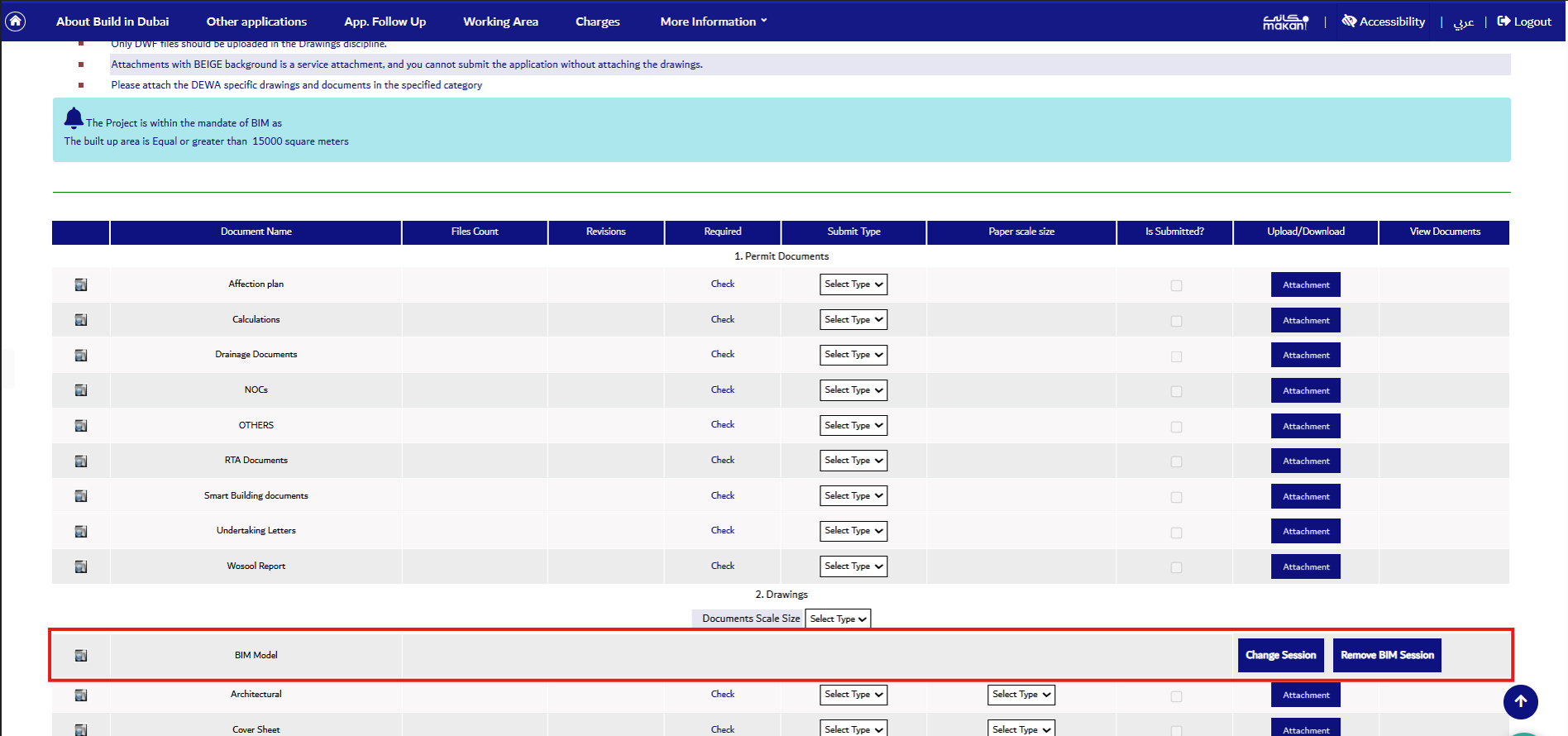
Important Notes
The BIM session may be changed or replaced prior to submission of the application
Once the application is submitted, the linked BIM session cannot be modified
The same BIM session shall be used for any subsequent revisions or resubmissions related to the permit
SOFTWARE-SPECIFIC TECHNICAL GUIDELINES
AUTODESK REVIT SOFTWARE
INTRODUCTION
This section provides software-specific implementation guidance for BIM model development using Autodesk Revit. While this section is structured around Revit, several of the principles and requirements outlined such as model structuring, information population, classification, and IFC export are highly applicable to other BIM authoring tools.
This section shall be used in conjunction with PART 2 – MODEL DEVELOPMENT.
It is important to note that the Dubai BIM Standard is software-agnostic and does not mandate the use of any specific BIM authoring platform. The software-specific guidance provided in this section is intended as a recommendation only. Model authors are responsible for implementing the requirements of the standard using their preferred BIM tools, provided that the final deliverables meet all submission requirements.
Compliance with Dubai Municipality requirements is assessed based on the exported IFC models, not on the native authoring file (e.g., Revit model). Therefore, users should ensure that all geometrical and alphanumerical information is correctly translated into the IFC output, as this will be the basis for validation, automated checking, and regulatory review.
Sample Autodesk Revit models developed by the Dubai Municipality team may be downloaded from https://buildindubai.gov.ae/bim website to provide a better understanding of the recommended modelling practices, IFC classification workflow, and attribute population requirements. The sample models are currently prepared in Revit version 2024
REVIT TEMPLATE
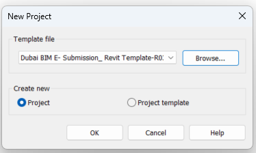
When Autodesk Revit is used as the BIM authoring tool, it is recommended that the Dubai BIM E-Submission Template for Revit is used. The latest version of the template can be downloaded from: https://buildindubai.gov.ae/bim.
The template is currently in the Revit Version 2023. It is recommended that Revit version 2023 or above be used for the preparation of models intended for BIM E-Submission. Where higher versions are used, the template shall be upgraded accordingly prior to modelling.
The Dubai BIM E-Submission Template includes:
Shared parameters aligned with Appendix B (Model Attribute Matrix)
Predefined naming conventions for levels, views, families etc
Element categorisation
Schedules and Key schedules
IFC export settings – (Model View Definition – IFC4 Reference View)
The use of the template is recommended but not mandatory. Where a company-standard template is used instead, it is the responsibility of the Model Author to ensure that all required attributes, parameter mappings, IFC export settings, property sets, and classification rules fully comply with the Dubai BIM Standard and E-Submission requirements.
MODEL CREATION
There are no restrictions on how Revit users create and develop their BIM models. However, it is essential that the model authoring team fully understands the applicable requirements and permissible approaches related to model structuring and segregation for submission and adopts modelling practices that support compliance with submission requirements. This includes the proper structuring of buildings, disciplines, and model elements in preparation for IFC export.
The Dubai BIM Standard, particularly the Model Segregation requirements, together with Section 2.5 of this document, define the governing rules for model organization and separation. Further detailed guidance on model splitting for Revit users is provided in Section 5.1.6.3 of this document.
PROJECT INITIALIZATION
The Model Author can start a new project using the Dubai BIM E-Submission Template for Revit from the designated location. Where a company-standard template is used instead, it shall be verified prior to project initiation that all required parameters, settings, and IFC configurations have been fully incorporated in accordance with the Dubai BIM Standard.
PROJECT LEVEL SETUP
The Dubai BIM E-Submission Template for Revit includes a set of basic levels. Additional levels may be created as required; however, all level naming conventions shall comply with the Dubai BIM Standard. It is mandatory that all models submitted to the Authority include a GA_GATE LEVEL. The GA_GATE LEVEL shall be established as the primary reference level and aligned with the project “Internal Origin” at the start of the modelling process. This ensures that the Z-value of the IFC “IfcSite” corresponds correctly to the GA_GATE LEVEL elevation.
Where necessary, dummy levels or reference levels may be introduced to support the modelling process. However, such levels shall be excluded from IFC export by ensuring that the Revit “Building Story” parameter is disabled for those levels.
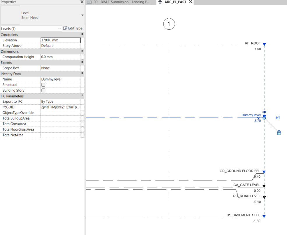
Figure 31. Building Story option
MODEL SCHEDULE/SHARED PARAMETERS
Where company standard templates are used, shared parameters, schedules and key schedules can be used from the Dubai BIM E-Submission Template, to enhance the company template with the required configuration for submission. The schedules provided within the template can be used to validate completeness and correctness of IFC data. Where company standard templates are used, users can create custom schedules to populate the parameter values. Where required, third-party tools or Dynamo scripts may be used to improve efficiency.
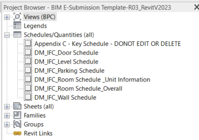
Figure 32. MODEL SCHEDULE
- SHARED PARAMETERS
The required shared parameters are preloaded within the Dubai BIM E-Submission Template to allow direct data entry. Below are the steps to load the shared parameters to company standard templates.
- Navigate to Manage Ribbon Tab, Under Settings panel select “Project Parameters”

Figure 33. Manage -> Project Parameters
- Click the icon to create a new parameter
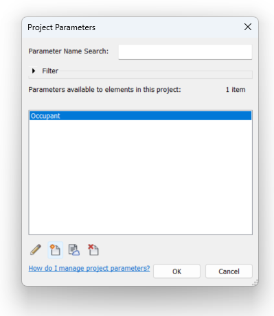
Figure 34. Project Parameters
- Under Parameter type, select “Shared Parameter” and click “select”
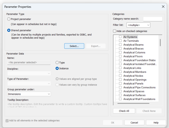
Figure 35. Parameter Properties
- Click “Edit” to display the Shared Parameters dialog box
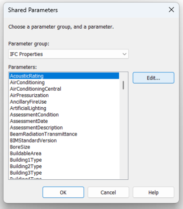
Figure 36. Shared Parameter
- Click “Browse” and load the shared parameter file from the BIM Standards package.
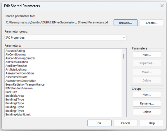
Figure 37. Edit Shared Parameters
- Select the parameter to be added and click OK
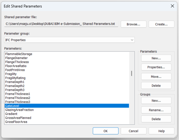
Figure 38. Edit Shared Parameters
- Under Parameter Data, set the parameter selected to Instance and group parameters to “IFC Parameters”. Ensure correct category assignment for each parameter.

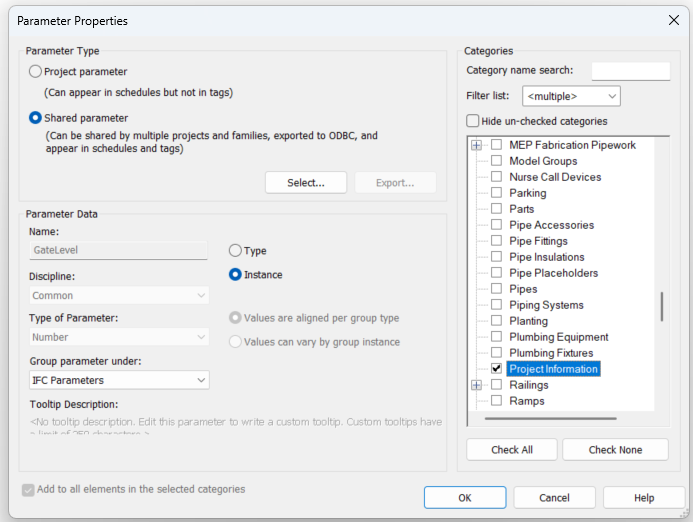
- KEY SCHEDULE
A Key Schedule corresponding to Appendix C is included within the template to facilitate the accurate and automated assignment of usage codes. Use the parameter named Room Style under Identity Data to select the SpaceUsageDescription for the room, then the SpaceUsageDescription, SpaceUsageCode, ZoneObjectType, ZoneName parameters will be filled automatically.
It is important to note that any modification made to the values within the provided Key Schedules may result in critical issues related to Space/Room information during QA/QC and Building Card generation. Therefore, Model Authors should not modify the Key Schedules provided within the Dubai BIM E-Submission template.
For users working within a company-standard template, the Dubai BIM E-Submission template should first be opened as a project, and the Appendix C - Key Schedule should then be transferred into the working file using the Insert from File option under Insert tab.
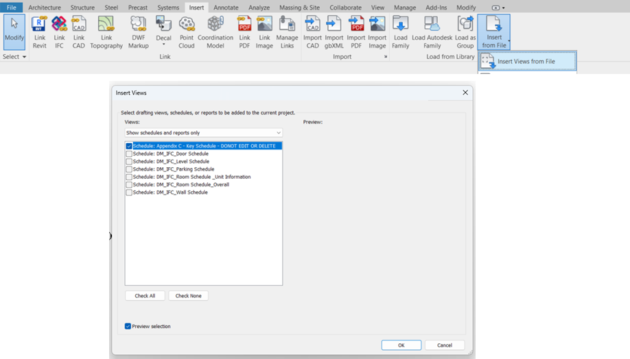
Figure 39. Insert View
MODEL ELEMENT ATTRIBUTES
To ensure successful BIM E-Submission, all required model attributes shall be correctly defined, assigned, and exported in accordance with Appendix B – Model Attribute Matrix.
All model elements shall contain the required parameters relevant to their type, including both mandatory and conditional attributes. Missing or incorrectly assigned attributes may result in validation errors, incomplete IFC data, and rejection of the submission.
The attributes that are available under the two property sets (the IFC standard property set and the custom "Building Permit" property set) need ONLY be filled in under the standard IFC property set. During IFC export, Revit IFC Exporter automatically populates the same values to the “Building Permit” property set, when the “Dubai BIM E-Submission_Property Sets” file is used during the IFC export
IfcSpatialContainer – This is an OPTIONAL parameter available for Autodesk Revit users, that can be used only in cases where an element is not assigned to its intended Building Storey during IFC export. In such cases, the correct level name shall be assigned to this parameter to ensure proper spatial assignment within the IFC model.
REVIT FAMILIES
The preloaded families available within the BIM E-Submission Revit template may be used for modelling purposes. Where additional families are required, they should be created in accordance with the design requirements or derived by duplicating and modifying existing families within the template. Prior to IFC export, all unused or redundant families shall be purged to ensure model optimization.
Ensure that there are no unreferenced model elements by checking that all elements created in Revit are referenced to a level. Model elements like walls and columns shall be modelled at their corresponding levels. This allows for the footprint area of walls and columns to be calculated in each level for BUA, GA, and GFA. Models submitted to Dubai Municipality shall not include elements modelled across multiple levels (e.g., from ground to roof as a single unsegmented element), where level-based hosting is required.
IFC ELEMENT MAPPING
All model elements shall be correctly mapped to the appropriate IFC class/type and exported using IFC4 Schema. This includes defining the appropriate PredefinedType where it exists within the IFC schema. Where a standard PredefinedType doesn’t exist, or where further specification is required, the ObjectTypeOverride parameter shall be used to provide additional details. The Revit Schedule feature may be used to validate IFC element class prior to export, ensuring completeness and consistency.
For Revit 2023 and newer, populate the built-in “Export to IFC As” parameter right from the property palette

- Click the 3 dots icon to open the IFC entity selector

- Search for the IFC entity and select the required one also choose its Predefined Type and select OK.
- If the Predefined type is not a standard in the IFC Schema or requires an extra identification, provide the parameter ObjectTypeOverride. Refer to Appendix B_Model Attribute Matrix, for the ObjectTypeOverride sample data.
 .
.
- If any element is not necessary to be exported to IFC, set the “Export to IFC” as NO

MODEL GEOREFERENCING
All Revit models submitted to the BIM E-Submission platform shall be georeferenced for integration with the Dubai GIS database. This integration is handled automatically by the platform, but it is a prerequisite that all IFC models host valid georeferencing information. It is the responsibility of the model author to ensure that an appropriate and accurate georeferencing method is applied.
It is highly recommended that the model be geo-referenced in the early stages of modelling to identify and rectify any georeferencing issues before the model progresses, when such issues become more difficult to correct.
The recommended procedure to geo-reference the model:
Obtain the GIS information as described in Section 2.6.
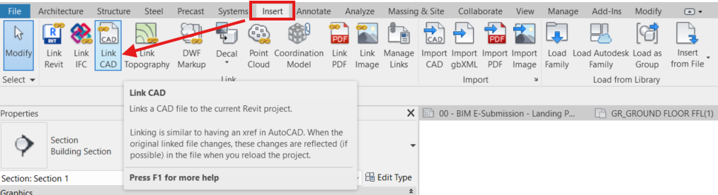
In Revit, navigate to the Insert tab and select the “Link CAD” option.
- Select the DWG file and configure the import settings
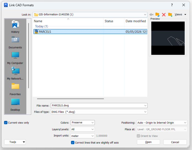
Place the linked .dwg file in the appropriate location within the Revit model.
Navigate to the “Manage” tab →” Coordinates” and select “Acquire Coordinates”. Then select the linked dwg file to import the coordinate system into the Revit model.
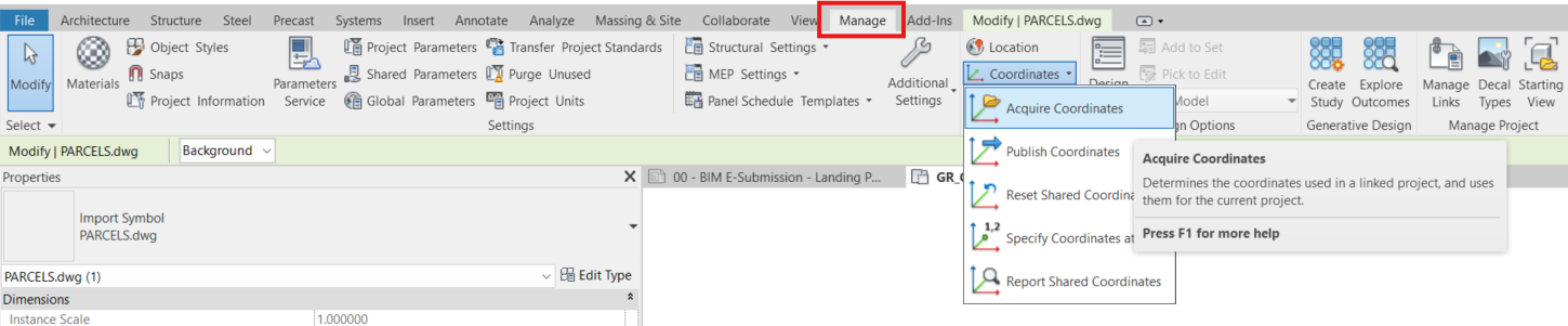
The model will now be aligned with the correct coordinate system.
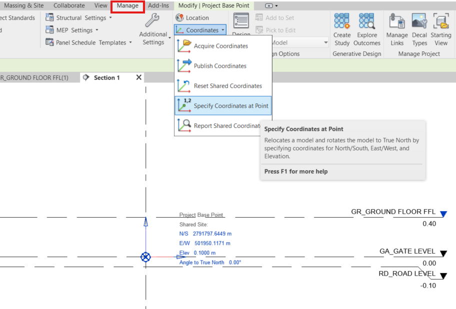
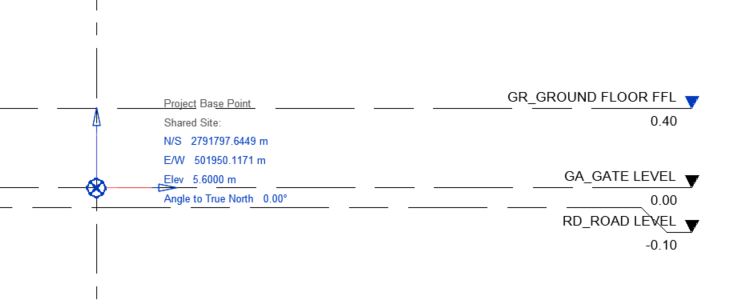
Create a section view and verify alignment between Project Base Point and internal Origin to GA_GATE LEVEL reference. This will ensure the Global Z coordinate for the IfcSite in the IFC model equal to the Gate level input.
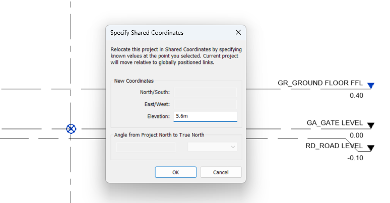
Navigate to “Manage” → “Coordinates” and select” Specify Coordinates at Point”. Pick the gate level and input the project DMD elevation value in meters. With this, when the model is exported to IFC, the IfcBuildingStorey for the GA_GateLevel level will have a global Z value equal to DMD level.
MODEL COORDINATION AND CLASH DETECTION
All models developed in Autodesk Revit shall be in compliance with Section 2.7.
MODEL EXPORT
Once the model setup has been completed in accordance with the requirements outlined above, the BIM model is considered ready for export to IFC format. It is recommended that a dedicated 3D view is maintained specifically for BIM E-Submission export to ensure consistency during each export process. All IFC exports should be performed from this predefined view. The models shall be exported in IFC4 Reference View.
REVIT IFC EXPORTER
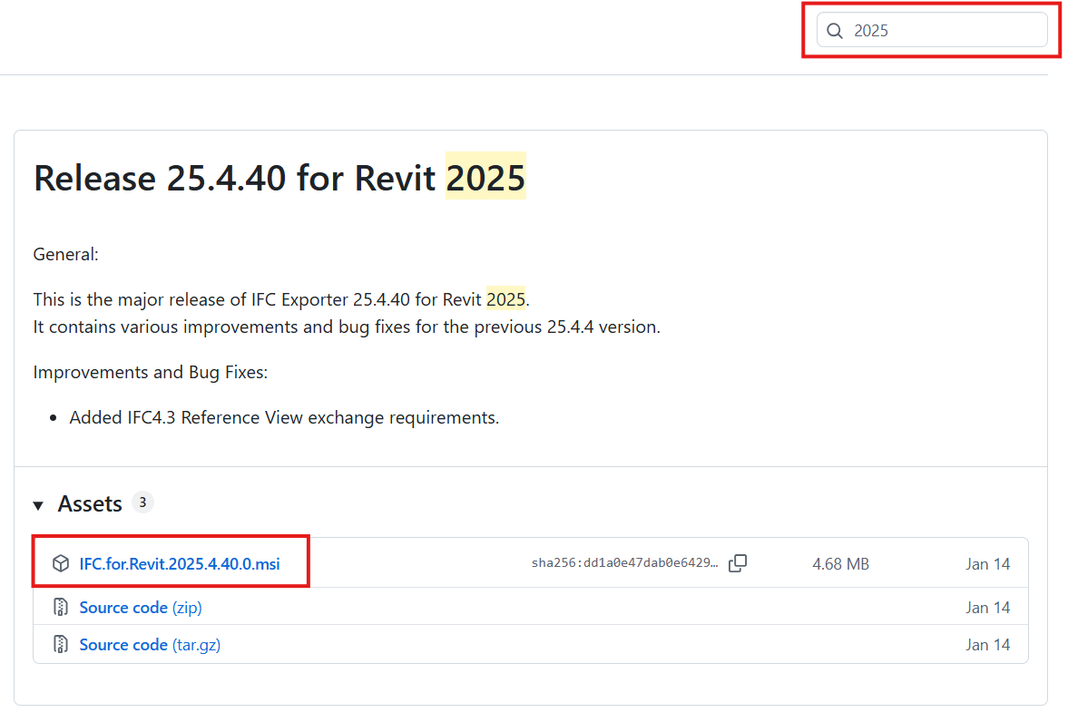
Prior to exporting the model from Autodesk Revit to IFC, it shall be ensured that the latest version of the IFC Exporter for Revit is installed. The exporter can be downloaded for the respective Revit versions (e.g., 2023, 2024, etc.) from the Autodesk IFC GitHub repository.
Go to the Autodesk IFC GitHub page, search for the Revit version and select the latest version and the “.msi” file under “Asset” section should be downloaded and installed to ensure compatibility and compliance with IFC export requirements
MODEL UNIT
The model units shall be set to [meters]{.underline} prior to IFC export. IFC files exported in any other unit will not be accepted by the BIM E-Submission Platform. Where project units are maintained in any other working units for documentation purposes, the units shall be temporarily converted to meters prior to export. Upon completion of the export process, the units may be reverted to the required working units.
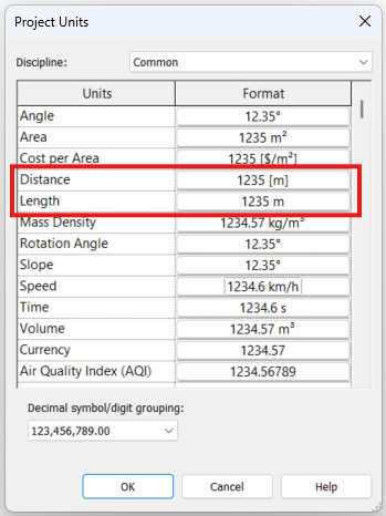
MODEL SPLIT
Before exporting the BIM model to a set of IFC files, the model author should decide how this will be done. Beside the details below on some recommendations, the user shall follow the rules define in Section 2.5 (MODEL SEGREGATION).
1. Parcel with Single building
When the building is not complex or large, the model split should be easy, but for complex or high-rise developments, it is recommended that the model is divided into smaller parts prior to IFC export. Exporting a single, large model may result in extended processing times or potential export failures. Model splitting is not mandatory and remains at the discretion of the Model Author. This process may be achieved using section boxes defined as required. It shall be ensured that model elements are not duplicated across multiple exported parts. In this scenario, the BuildingNum parameter under Project Information shall remain consistent across all model parts (recommended to start from 1), while the BuildingPartNum parameter shall remain empty. If the Architectural model is split into parts, it is not mandatory that all the other models should also be exported as parts, the Structural model can still be exported as a single IFC export. All exported IFC files shall comply with the prescribed file naming convention.
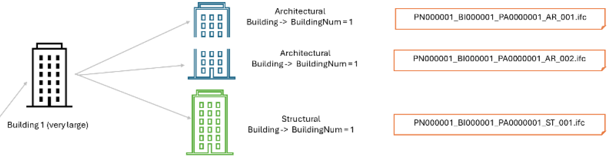
2. Parcel with Single Building - Multiple Towers
Where the project consists of multiple towers sharing a common podium or basement, each tower shall be treated as an individual BIM model. The podium or basement may be developed as a separate model. In this case, the BuildingNum parameter shall remain the same across all models (recommended to start from 1). The BuildingPartNum parameter shall be assigned incrementally (starting from 1) for all Building Storeys within each respective model. All exported IFC files shall comply with the prescribed file naming convention.
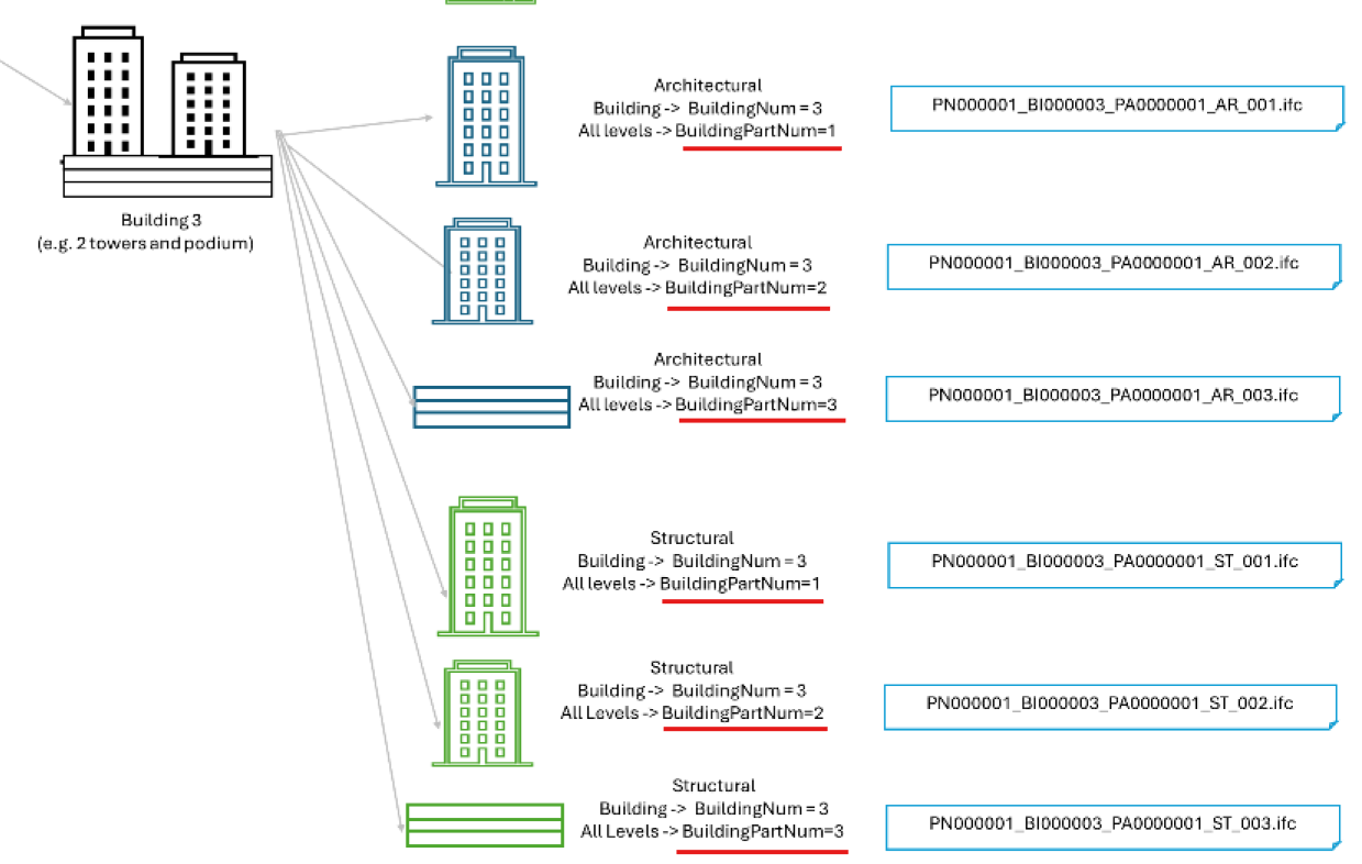
3. Parcel with Multiple Buildings
Where a parcel contains multiple buildings, including annex or auxiliary structures (such as substations or security cabins), it is mandatory to develop separate Revit models and corresponding IFC files for each building. In this scenario, the BuildingNum parameter under Project Information shall be assigned incrementally (starting from 1) across the different models, while the BuildingPartNum parameter shall remain empty. All exported IFC files shall comply with the prescribed file naming convention.
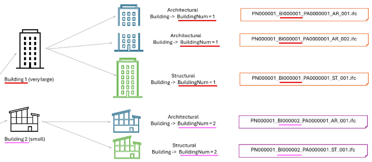
EXPORT SETUP REVIT 2023- 2024
The following steps shall be followed to export the model from Autodesk Revit to IFC:
- Navigate to File 🡪 Export 🡪 Option 🡪 IFC Option
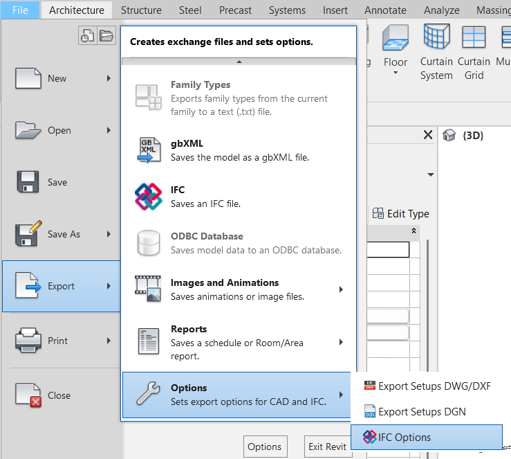
- Select “Load” and browse to the file named “Dubai BIM E-Submission_IFC Parameter Mapping”, located under Templates 🡪 Revit folder within the BIM Standards package downloaded from the Build in Dubai portal.\ It is recommended that the IFC parameter mapping file is always loaded from a local drive rather than from a server or cloud location.
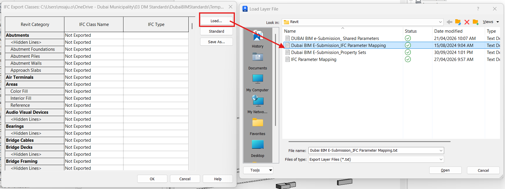
Navigate to File 🡪 Export 🡪 IFC
Select the desired export location and assign an appropriate file name in accordance with the naming convention.
Select “Modify setup”
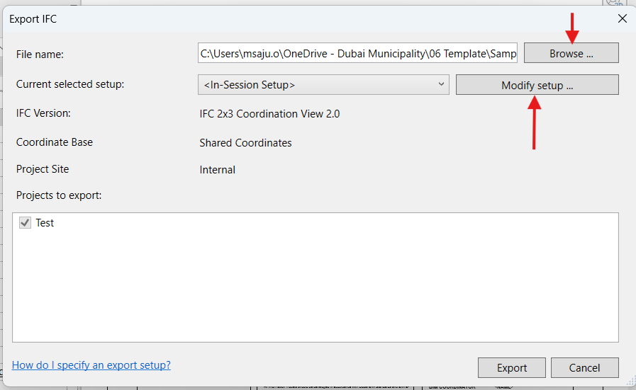
- Import the predefined BIM E-Submission export setup by selecting “Import Setup”, then browse and select the corresponding “.json” file located under Templates 🡪 Revit folder within the BIM Standards package downloaded from the Build in Dubai portal.
If the Model Author is using the Dubai BIM E-Submission Template, the export setup is already preloaded within the template and does not need to be imported again. In such cases, the preloaded setup shall be selected and used for the IFC export process.
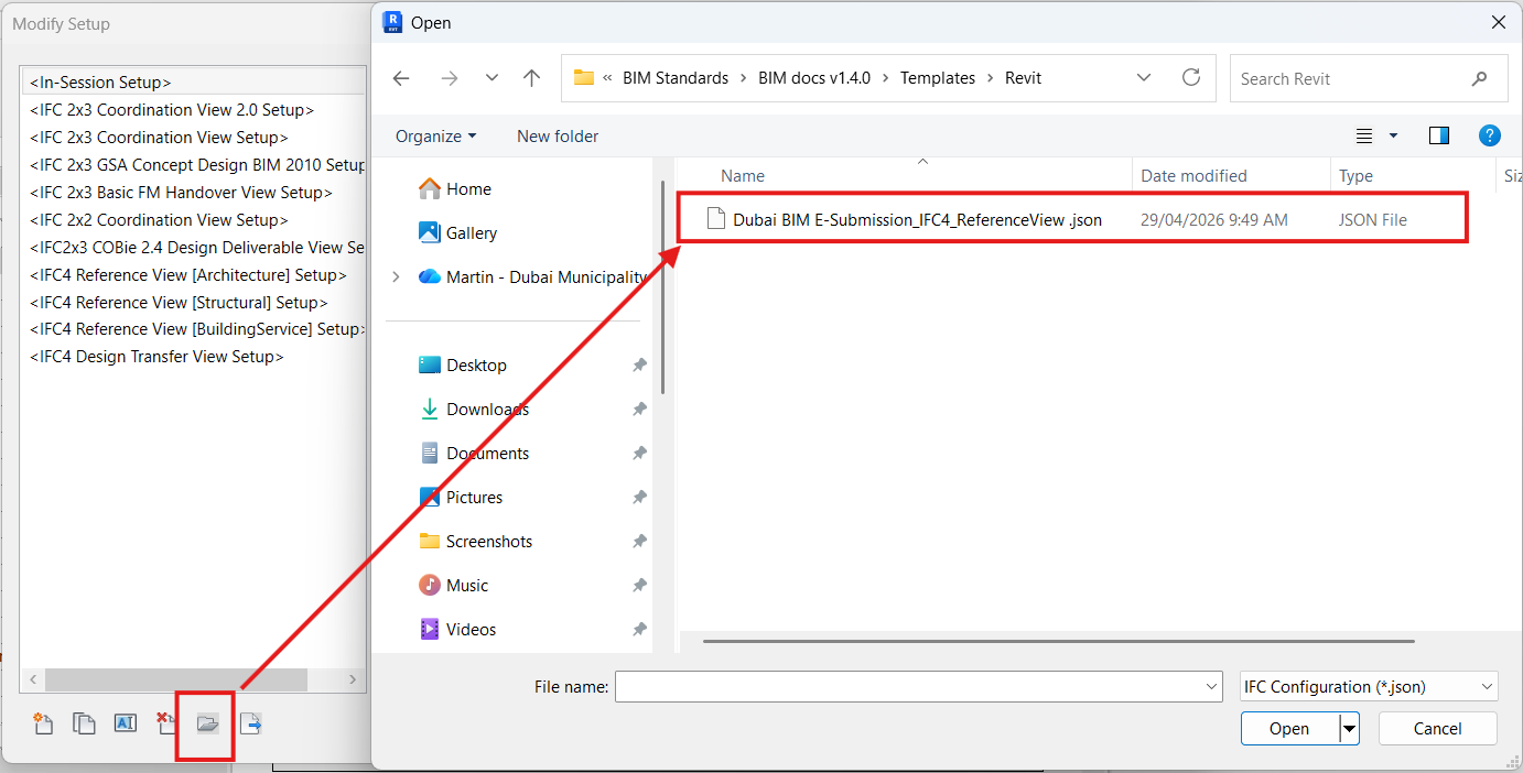
Once the setup is imported, all export settings will be automatically configured in accordance with Dubai Municipality BIM E-Submission requirements. After the setup has been loaded into the project, it is not required to import it again before every export. However, it shall be ensured that the correct export setup is selected during each IFC export operation. The IFC version shall always be set to IFC4 Reference View.
Navigate to “Additional Content” tab and make sure the Revit links are not exported. All linked Revit models should be exported from the corresponding BIM models only
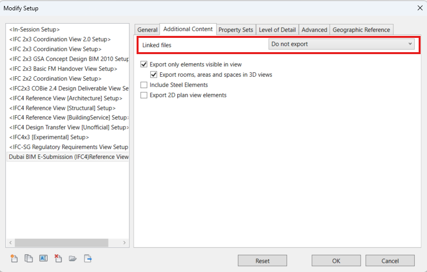
- Navigate to the “Property Sets” tab and load the required Property Set file from Templates 🡪 Revit folder within the BIM Standards package. It is recommended that this file is also loaded from a local drive.
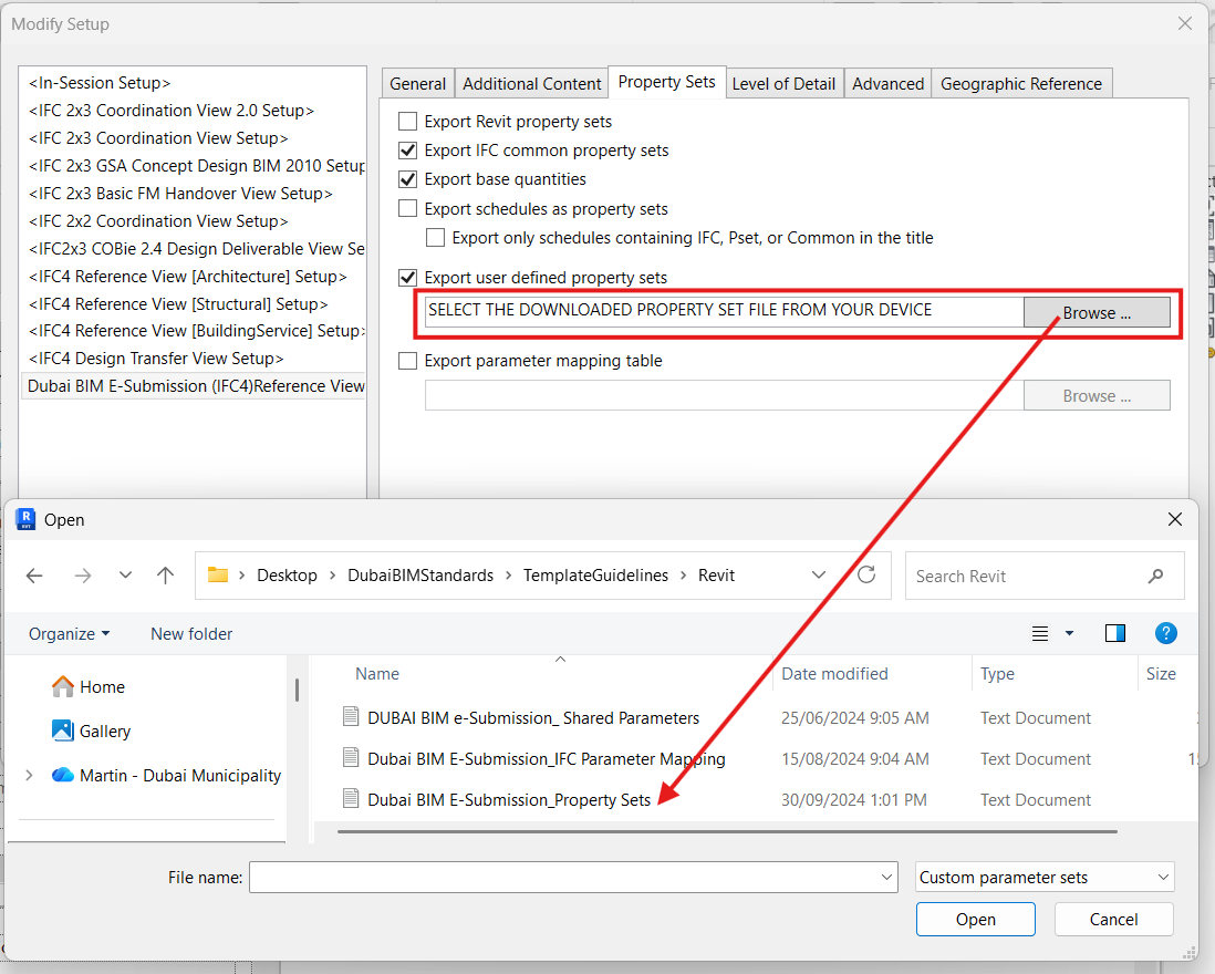
- Navigate to the “Geographic Reference” tab and ensure that the coordinate base is set to [Shared Coordinates]{.underline}. No overrides shall be applied to the Projected Coordinate System Reference.
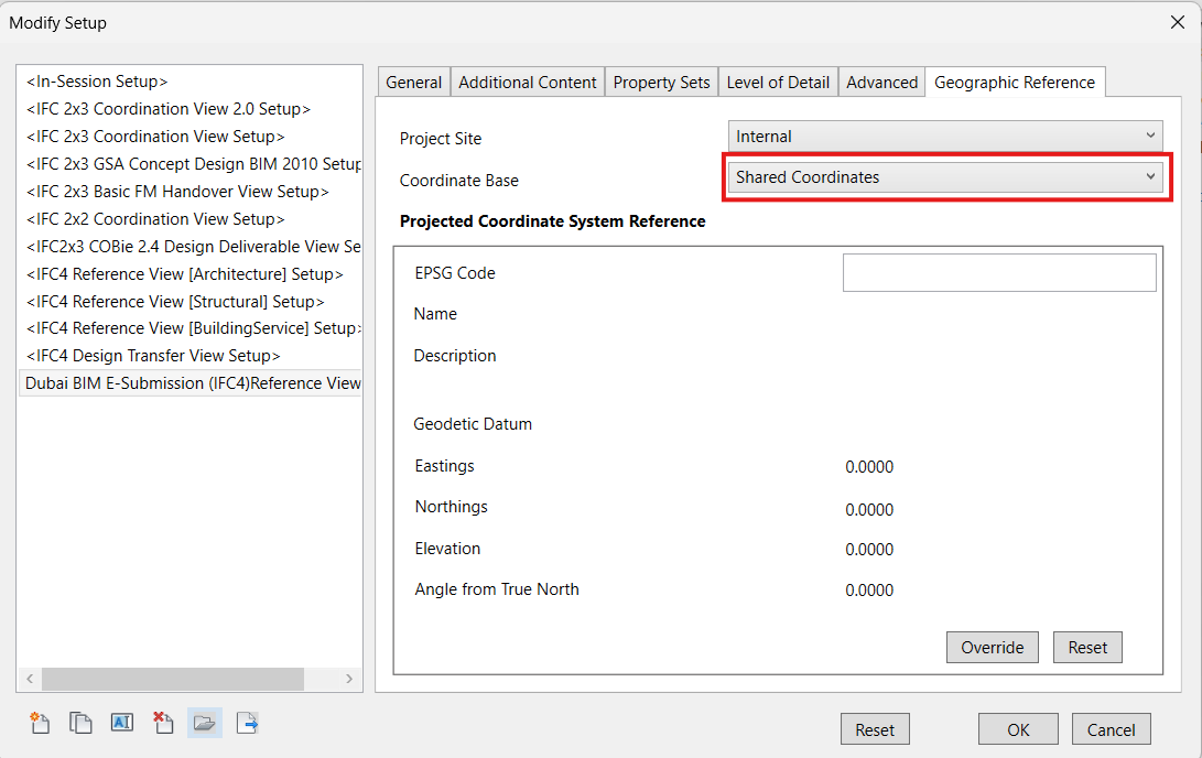
- Select OK and click “Export” to generate the IFC file from the Revit model.
EXPORT SETUP REVIT 2025
Navigate to File 🡪 Export 🡪 IFC
Select the desired export location and assign an appropriate file name in accordance with the naming convention.
Select “Modify setup”
- Import the predefined BIM E-Submission export setup by selecting “Import Setup”, then browse and select the “.json” file located under Templates 🡪 Revit within the BIM Standards package downloaded from the Build in Dubai portal.
If the Model Author is using the Dubai BIM E-Submission Template, the export setup is already preloaded within the template and does not need to be imported again. In such cases, the preloaded setup shall be selected and used for the IFC export process.
Once the setup is imported, all export settings will be automatically configured in accordance with Dubai Municipality BIM E-Submission requirements. After the setup has been loaded into the project, it is not required to import it again before every export. However, it shall be ensured that the correct export setup is selected during each IFC export operation. The IFC version shall always be set to IFC4 Reference View.
Unlike Revit 2023 -2024 versions, category mapping is loaded from the “General” tab itself. For that hit the three dots near to the “Category Mapping” and click “Import Template” icon and load the “Dubai BIM E-Submission_Parameter Mapping” file from Templates 🡪 Revit folder within the BIM Standards package.
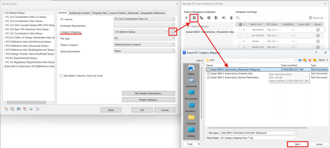
- Once the Parameter mapping is loaded, select the file from the dropdown in “Category Mapping”.
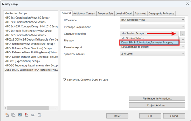
- Navigate to “Additional Content” tab and make sure the Revit links are not exported. All linked Revit models should be exported from the corresponding BIM models only
- Navigate to the “Property Sets” tab and load the Property Set file from Templates 🡪 Revit folder within the BIM Standards package. It is recommended that this file is also loaded from a local drive.
- Navigate to the “Geographic Reference” tab and ensure that the coordinate base is set to [Shared Coordinates]{.underline}. No overrides shall be applied to the Projected Coordinate System Reference.
- Select OK and click “Export” to generate the IFC file from the Revit model.
GRAPHISOFT ARCHICAD SOFTWARE
INTRODUCTION
This section provides software-specific implementation guidance for BIM model development using ArchiCAD. While this section is structured around ArchiCAD, several of the principles and requirements outlined such as model structuring, information population, classification, and IFC export are highly applicable to other BIM authoring tools.
This section shall be used in conjunction with PART 2 – MODEL DEVELOPMENT.
It is important to note that the Dubai BIM Standard is software-agnostic and does not mandate the use of any specific BIM authoring platform. The software-specific guidance provided in this section is intended as a recommendation only. Model authors are responsible for implementing the requirements of the standard using their preferred BIM tools, provided that the final deliverables meet all submission requirements.
Compliance with Dubai Municipality requirements is assessed based on the exported IFC models, not on the native authoring file. Therefore, users should ensure that all geometrical and alphanumerical information is correctly translated into the IFC output, as this will be the basis for validation, automated checking, and regulatory review.
ARCHICAD TEMPLATE
When ArchiCAD is used as the BIM authoring tool, it is recommended that the Dubai BIM E-Submission Template for ArchiCAD is used. The latest version of the template can be downloaded from: https://buildindubai.gov.ae/bim.
The template consists of pre-defined properties, settings, views and objects, that will aid model consistency and efficiency, which will allow for the automation of modeling tasks and ensure a smoother process when uploading the model and the BIM E-Submission platform.
MODEL CREATION
There are no restrictions on how ArchiCAD users create and develop their BIM models. However, it is essential that the model authoring team fully understands the applicable requirements and permissible approaches related to model structuring and segregation for submission and adopts modelling practices that support compliance with submission requirements. This includes the proper structuring of buildings, disciplines, and model elements in preparation for IFC export.
The Dubai BIM Standard, particularly the Model Segregation requirements, together with Section 2.5 of this document, define the governing rules for model organization and separation.
PROJECT INITIALIZATION
The Model Author can start a new project using the Dubai BIM E-Submission Template for ArchiCAD from the designated location. Where a company-standard template is used instead, it shall be verified prior to project initiation that all required parameters, settings, and IFC configurations have been fully incorporated in accordance with the Dubai BIM Standard.
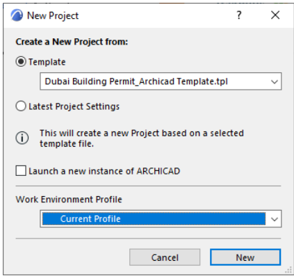
PROJECT LEVEL SETUP
The template file has some predefined storeys. These storeys are named as per the naming outlined the BIM Standard (Level Naming). The user is free to add or delete storeys as is necessary for the project but should adhere to the required naming if adding additional levels.
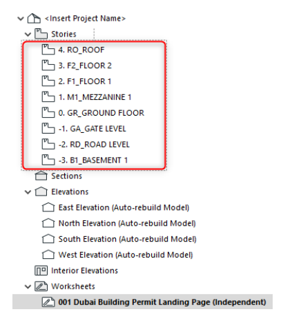
MODEL GEOREFERENCING
All ArchiCAD models uploaded to the BIM E-Submission platform must be georeferenced for integration with the Dubai GIS database. This integration is handled automatically by the platform, but it is a prerequisite that all IFC models host valid georeferencing information.
It is highly recommended that the model be geo-referenced in the early stages of modelling to identify and rectify any georeferencing issues before the model progresses, when such issues become more difficult to correct.
The recommended procedure to geo-reference the model:
Obtain the GIS information as described in Section 2.6.
The user must identify a real-world coordinate on the land parcel and reflect that point as the survey point in ArchiCAD. As a default in the template file, the survey point placed at gridline A-1 as the project origin point.
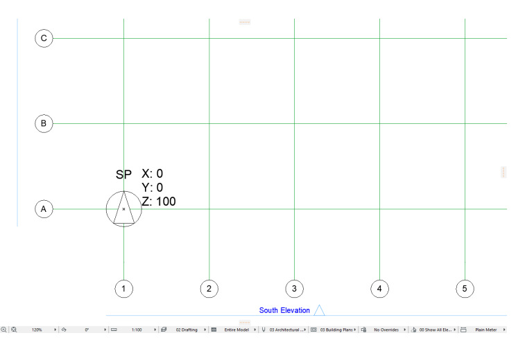
EXPORT TO IFC
The ArchiCAD template has incorporated IFC translators for both IFC2x3 and IFC4. When users are exporting to IFC for the purpose of uploading to the BIM E-Submission platform, they must use these predefined translators.
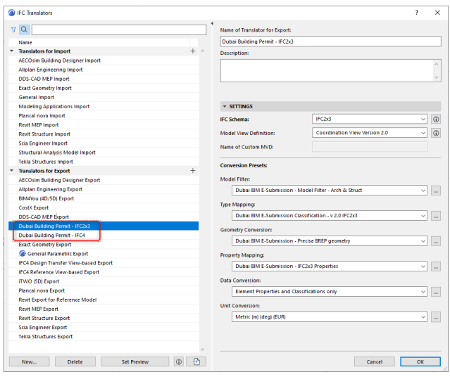
Within the IFC Translator window, there is a “Settings” section to the right-hand side (see figure below). These settings contain all the preferences for the IFC Translator the user has selected. The Dubai Building Permit translators have predefined conversion presets, and these presets should not be changed.
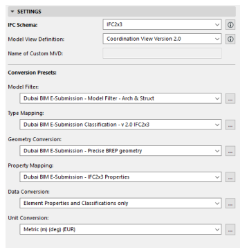
When the user is ready to export, they should click “File” and “Save as”, this will show a new window, as shown in the figure below. In this window, the user can select the translator they wish to use and should also define the file name as per the BIM Standard naming requirements.
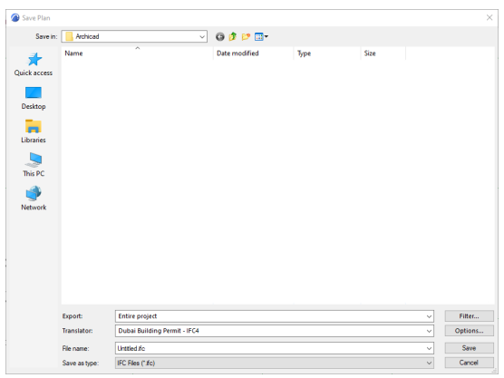
In the “Save as” window above, the user can select the “Options” button to view and ensure that the translator selected has all the relevant conversion presets assigned.